Isuzu KB P190. Manual - part 751


  Index      Isuzu     Isuzu KB P190 - service repair manual 2007 year


Search            


Content   ..  749  750  751  752   ..


Isuzu KB P190. Manual - part 751


Engine Mechanical – V6 

Page 6A1–227 


Page 6A1–227 

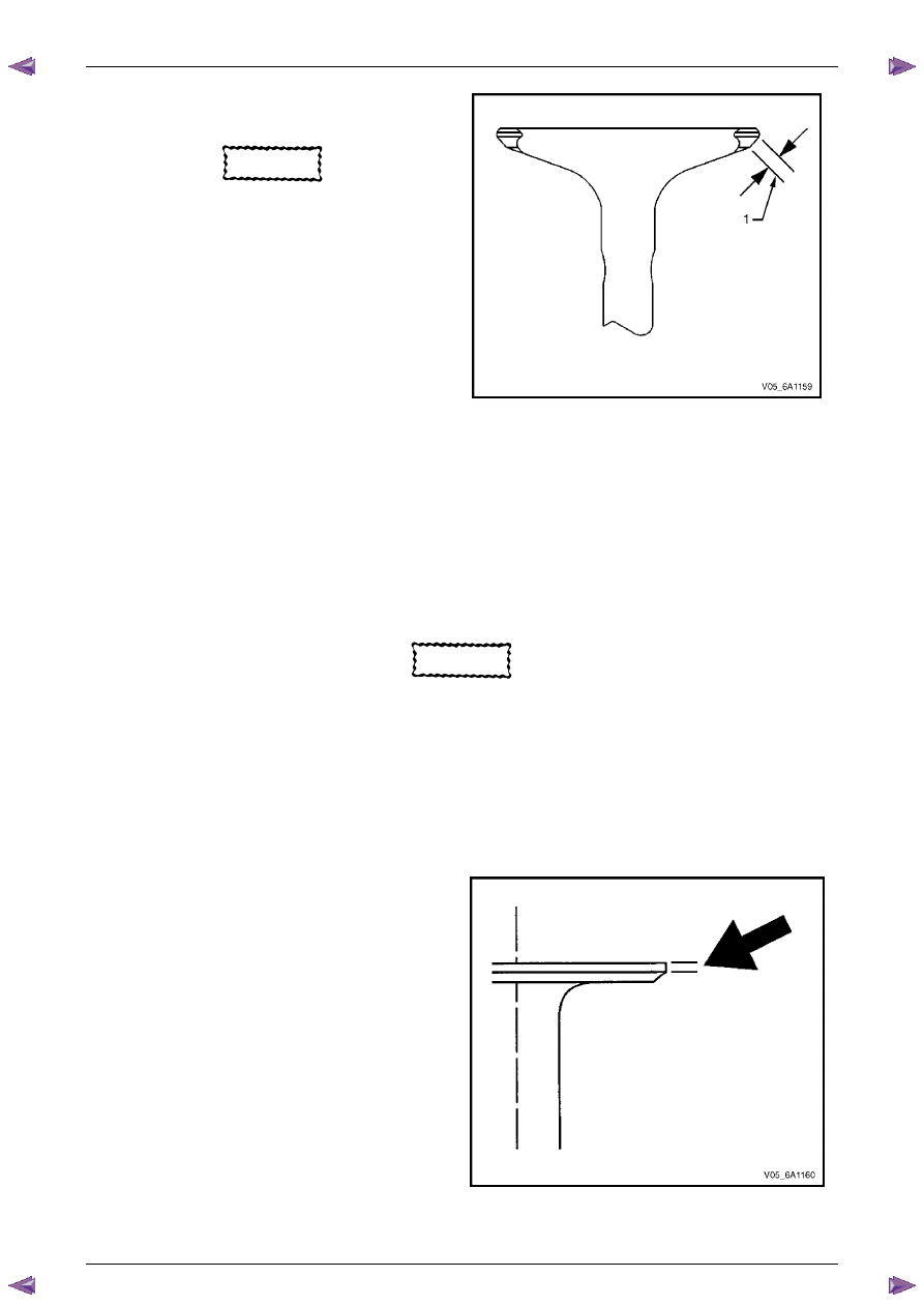
Measure the seat width on the valve face (1) using a 
correct scale. 

CAUTION


The seat contact area must be at least 
0.5 mm from the outer diameter (margin) of 
the valve. If the contact area is too close to 
the margins, the seat must be reconditioned 
to move the contact area away from the 
margin. 

Compare the measurements with the specifications, 
refer to 

5  Specifications

If the seat widths are acceptable, check the valve 
seat roundness, refer to Valve Seat Roundness 
Measurement Procedure in this Section. 

If the seat width is not acceptable, grind the valve 
seat to bring the width back to specification. Correct 
valve seat width is critical to providing the correct 
amount of valve heat dissipation, refer to Valve and 
Seat Reconditioning Procedure in this Section. 


Figure 6A1 – 383 

Valve Seat Roundness Measurement Procedure 

Measure the valve seat roundness using a dial indicator attached to a tapered pilot installed in the guide. The pilot 
should have a slight bind when installed in the guide. 

CAUTION


The correct size pilot must be used. Do not 
use adjustable diameter pilots. Adjustable 
pilots may damage the valve guides. 

Compare your measurements with the specifications, refer to 

5  Specifications

If the valve seat exceeds the roundness specification, grind the valve and valve seat, refer to Valve and Seat 
Reconditioning Procedure in this Section. 

If new valves are being used, the valve seat roundness must be within 0.05 mm. 

Valve Margin Measurement Procedure 

Measure the valve margin using an appropriate scale.

2 Refer 

to 

5  Specifications

 for minimum valve margin 

and compare them to your measurements. 

If the valve margins are beyond specification, replace 
the valves. 

If the valve margins are within specification and do 
not require refacing, test the valve for seat 
concentricity, refer to Valve-to-Seat Concentricity 
Measurement Procedure in this Section. 


Figure 6A1 – 384 

Engine Mechanical – V6 

Page 6A1–228 


Page 6A1–228 

Valve-to-Seat Concentricity Measurement Procedure 

Checking the valve-to-seat concentricity determines whether the valve and seat are sealing correctly. 

Measure the valve face and the valve seat to ensure correct valve sealing. 

Coat the valve face lightly with blue dye (3). 

Install the valve in the cylinder head. 

Turn the valve against the seat with enough pressure 
to wear off the dye. 

Remove the valve from the cylinder head. 

Inspect the valve face. 

N O T E  

• 

If the valve face is concentric, providing a 
correct seal, with the valve stem, a continuous 
mark (1) will be made around the entire face (2).

• 

The wear mark must be at least 0.5 mm from 
the margin of the valve. If the wear mark is too 
close to the margin, the seat must be 
reconditioned to move the contact area away 
from the margin. 

• 

If the face is not concentric with the stem, the 
mark will not be continuous around the valve 
face. The valve should be refaced or replaced 
and the seat must be reconditioned, refer to 
Valve and Seat Reconditioning Procedure in 
this Section. 


Figure 6A1 – 385 

Valve and Seat Reconditioning Procedure 

If the valve seat width, roundness or concentricity are beyond specifications, grind the seats in order to ensure correct 
heat dissipation and prevent the build up of carbon on the seats. 

If valve seat reconditioning is required, reface the valve face, unless a new valve is used. 

Grind the valve seats (2) to the correct angle 
specification, refer to 

5  Specifications

Using the correct angle specification, grind and 
relieve the valve seats (1) to correctly position the 
valve seating surface (2) to the valve. 

Using the correct angle specification, grind and 
undercut the valve seats (3) to narrow the valve seat 
widths to the specifications, refer to 

5  Specifications

If the original valve is being used, grind the valve to 
the specifications, refer to 

5  Specifications

. Measure 

the valve margin again after grinding, refer to Valve 
Margin Measurement Procedure in this Section. 
Replace the valve if the margin is out of specification. 
New valves do not require grinding. 

When grinding the valves and seats, grind off as little 
material as possible. Cutting valve seat results in 
lowering the valve spring pressure. 

Install the valve in the cylinder head. 


Figure 6A1 – 386 

CAUTION


If using refaced valves, lap the valves into the 
seats with a fine grinding compound. The 
refacing and reseating operations should 
leave the refinished surfaces smooth and true 
so that minimal lapping is required. Excessive 
lapping will groove the valve face and prevent 
a good seat when hot. 

Engine Mechanical – V6 

Page 6A1–229 


Page 6A1–229 

N O T E  

•  Clean any remaining lapping compound from 

the valve and seat with solvent and 
compressed air prior to final assembly. 

•  If fitting new valves, do not lap the valves 

under any condition. 


After obtaining the correct valve seat width in the cylinder head, measure the valve stem height, refer to Valve 
Stem Height Measurement Procedure in this Section. 

If the valve stem height is acceptable, test the seats for concentricity, refer to Valve-to-Seat Concentricity 
Measurement Procedure in this Section. 

Valve Stem Height Measurement Procedure 

CAUTION


To determine the valve stem height 
measurement, measure from the valve 
spring seat to the valve spring retainer. 

Install the valve into the valve guide. 

Ensure the valve is seated to the valve seat. 

Install the valve stem oil seal. 

Install the valve spring retainer and valve stem keys. 

Measure the distance (1) between the cylinder head 
to the bottom of the valve spring retainer, refer to  

5  Specifications

If the maximum height specification is exceeded, a 
new valve should be installed and the valve stem 
height re-measured. 


Figure 6A1 – 387 

CAUTION


Do not grind the valve stem tip. The tip of the 
valve is hardened and grinding the tip will 
eliminate the hardened surface causing 
premature wear and possible engine damage. 

CAUTION


Do not use shims to adjust valve stem height. 
The use of shims will cause the valve spring 
to bottom out before the camshaft lobe is at 
peak lift and engine damage could result. 

If the valve stem height still exceeds the maximum height specification, the cylinder head must be replaced. 

Engine Mechanical – V6 

Page 6A1–230 


Page 6A1–230 

Assemble 

Install the cylinder head coolant threaded plugs (1) 
and tighten to the correct torque specification.  


Cylinder head threaded plug ..............................31.0 Nm 


Figure 6A1 – 388 

Install the cylinder head oil gallery expansion 
plugs (1). 


Figure 6A1 – 389 

CAUTION


•  Never reuse a valve stem oil seal. Always 

use new seals when assembling the 
cylinder head. 

•  Force should only be applied to the valve 

spring contact area of the new valve stem 
oil seal during installation. 

Fit the valve stem oil seals onto the guides using Tool 
No. EN-46116 (1). 

Push and twist the valve stem oil seal into position on 
the valve guide until the seal positively locks on the 
guide using Tool No. EN-46116. 

Lubricate the valve stem and valve guide ID with 
clean engine oil. 


Figure 6A1 – 390 


Content   ..  749  750  751  752   ..