Isuzu KB P190. Manual - part 747
Engine Mechanical – V6
Page 6A1–211
Page 6A1–211
4
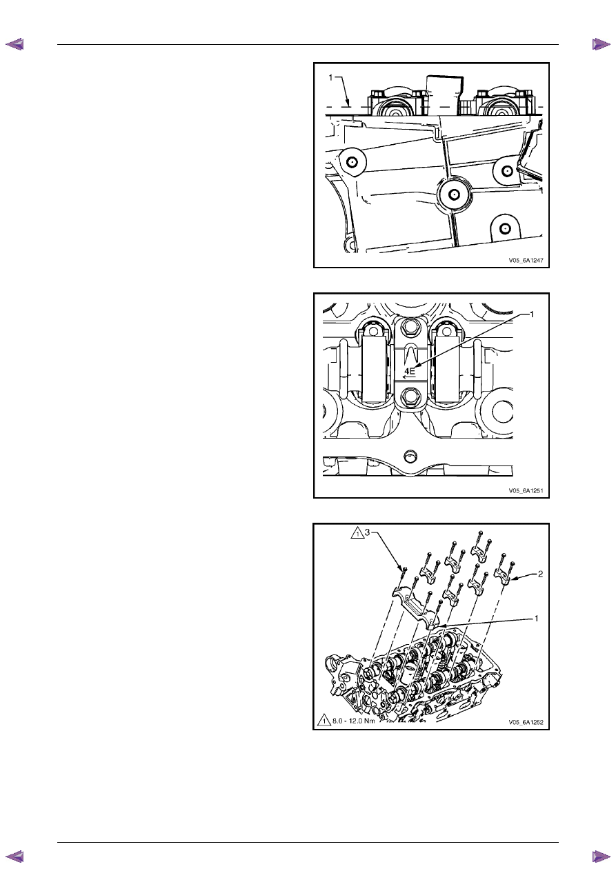
Ensure the camshaft lobes are in the neutral position
with the flats on the back of the camshafts up and
parallel (1) with the left-hand cylinder head camshaft
cover rail.
5
Ensure the marks on the left-hand exhaust camshaft
position actuator and timing chain, made prior to the
disassemble operation are aligned.
6
Ensure the marks on the left-hand intake camshaft
position actuator and timing chain, made prior to the
disassemble operation are aligned.
Figure 6A1 – 354
7
Observe the markings on the left-hand cylinder head
camshaft bearing caps. Each bearing cap is
marked (1) to identify its location. The markings have
the following meanings:
•
The raised feature must always be oriented
toward the centre of the cylinder head.
•
The I indicates the intake camshaft.
•
The E indicates the exhaust camshaft.
•
The number 2, 4, 6 indicates the cylinder
position from the front of the engine.
8
Apply a liberal amount of engine oil to the camshaft
bearing caps.
Figure 6A1 – 355
9
Install the camshaft bearing thrust cap (1) in the first
journal of the left-hand cylinder head.
10
Install the remaining bearing caps (2) with their
orientation mark toward the centre of the cylinder
head.
11
Hand start all the camshaft bearing cap bolts (3).
Figure 6A1 – 356