Isuzu KB P190. Manual - part 734


  Index      Isuzu     Isuzu KB P190 - service repair manual 2007 year


Search            


Content   ..  732  733  734  735   ..


Isuzu KB P190. Manual - part 734


Engine Mechanical – V6 

Page 6A1–159 


Page 6A1–159 

10 

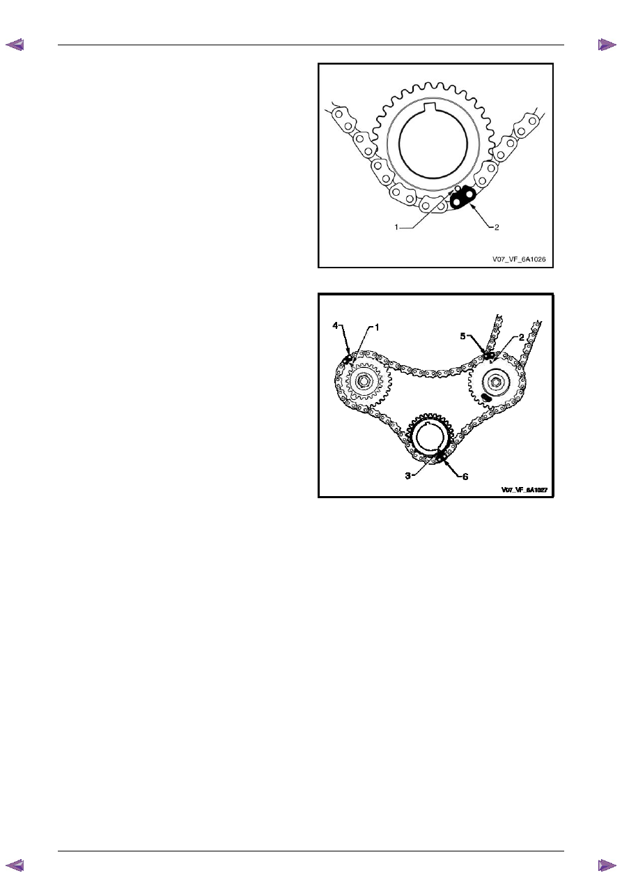
The crankshaft sprocket timing mark (1) will align with 
a bright plated timing chain link (2). 


Figure 6A1 – 226 

11 

Ensure all the timing marks (1, 2 and 3) are properly 
aligned with the bright plated timing chain links (4, 5 
and 6). 


Figure 6A1 – 227 

Engine Mechanical – V6 

Page 6A1–160 


Page 6A1–160 

N O T E  

Do not remove the primary timing chain lower 
guide (1). The primary timing chain lower guide 
is not serviced separately. If the primary timing 
chain lower guide must be replaced, the oil 
pump assembly (2) must be replaced.


Figure 6A1 – 228


12 

Ensure the primary timing chain upper guide is 
selected and orientated correctly. 


Figure 6A1 – 229 

13 

Install the primary timing chain upper guide (1). 

14 

Install the primary timing chain upper guide bolts (2) 
and tighten to the correct torque specification. 


Primary timing chain upper guide 
attaching bolt torque specification...........20.0 – 26.0 Nm 


Figure 6A1 – 230 

Engine Mechanical – V6 

Page 6A1–161 


Page 6A1–161 

15 

Ensure that the primary timing chain tensioner is 
being installed. 


Figure 6A1 – 231 

16 

Reset the primary timing chain tensioner. 


N O T E  

To reset the tensioner, use a suitably sized flat 
blade screwdriver (1) or Tool No. J 45027 (4) to 
wind the plunger in a clockwise direction, into 
the tensioner shaft (2). 


Figure 6A1 – 232 

17 

Install the tensioner shoe assembly (1) into the 
primary timing chain tensioner body (2). 


Figure 6A1 – 233 

Engine Mechanical – V6 

Page 6A1–162 


Page 6A1–162 

CAUTION


If Tool No. EN 46112 (1) is not inserted into 
the tensioner body, the plunger will remain 
in the locked position and no tension will be 
placed on the timing chain. 

18 

Compress the shoe assembly into the body (2) and 
lock the primary timing chain tensioner by inserting 
Tool No. EN 46112 into the access hole in the side of 
the body. 

19 

Slowly release pressure on the primary timing chain 
tensioner. The primary timing chain tensioner should 
remain compressed. 


Figure 6A1 – 234 

20 

Install a new primary timing chain tensioner gasket (1) 
to the tensioner (2). 

21 

Install the primary timing chain tensioner bolts (3) 
through tensioner and gasket. 

22 

Ensure the primary timing chain tensioner mounting 
surface on the engine block does not have any burrs 
or defects that would affect the sealing of the new 
gasket. 


Figure 6A1 – 235 

23 

Place the primary timing chain tensioner (2) into 
position and loosely install the bolts (1) to the engine 
block. 


Figure 6A1 – 236 


Content   ..  732  733  734  735   ..