Isuzu KB P190. Manual - part 699
Engine Mechanical – V6
Page 6A1–19
Page 6A1–19
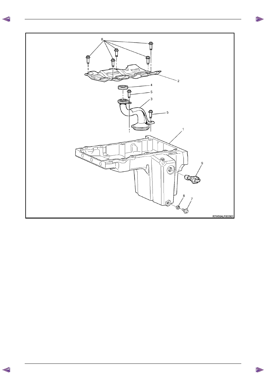
Oil Pan Assembly
Figure 6A1 – 11
Legend
1 Oil
Pan
2
Crankshaft Oil Deflector
3
Oil Pump Suction Pipe
4
Oil Pump Suction Pipe Gasket
5
Oil Pump Suction Pipe Bolt
6
Crankshaft Oil Deflector Bolt
7
Oil Pan Drain Plug
8
Oil Pan Drain Plug Sleeve
9
Engine Oil Level Sensor