Isuzu KB P190. Manual - part 677
Engine Mechanical – V6
Page 6A1–229
3
Measure the crankshaft thrust wall width (1) for wear
using an inside micrometer and compare with the
engine specifications, refer to 5
Specifications.
4
Measure the crankshaft thrust wall surface (2) for
runout using a dial indicator, mounted to a magnetic
stand and compare with the engine specifications,
refer to 5
Specifications.
5
If the crankshaft journals are damaged or worn
beyond specifications, the crankshaft may be ground
0.25 mm. There is only one size of oversized main
bearings available for service.
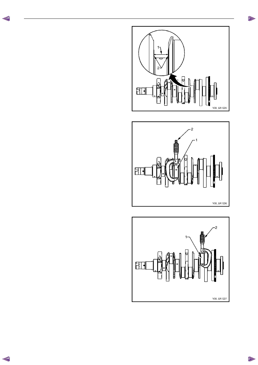
Figure 6A1 – 422
6
Inspect the crankshaft main journals (1) for undersize,
using an outside micrometer (2).
Figure 6A1 – 423
7
Inspect the crankpins (1) for undersize using an
outside micrometer (2).
8
Compare your measurements with those listed in the
engine specifications, refer to 5
Specifications.
If the crankpin journals are worn beyond the
specifications, the crankshaft may be ground 0.25
mm. Only one size of oversized connecting rod
bearings available for service.
Figure 6A1 – 424