Isuzu KB P190. Manual - part 673


  Index      Isuzu     Isuzu KB P190 - service repair manual 2007 year


Search            


Content   ..  671  672  673  674   ..


Isuzu KB P190. Manual - part 673


Engine Mechanical – V6 

Page 6A1–213 


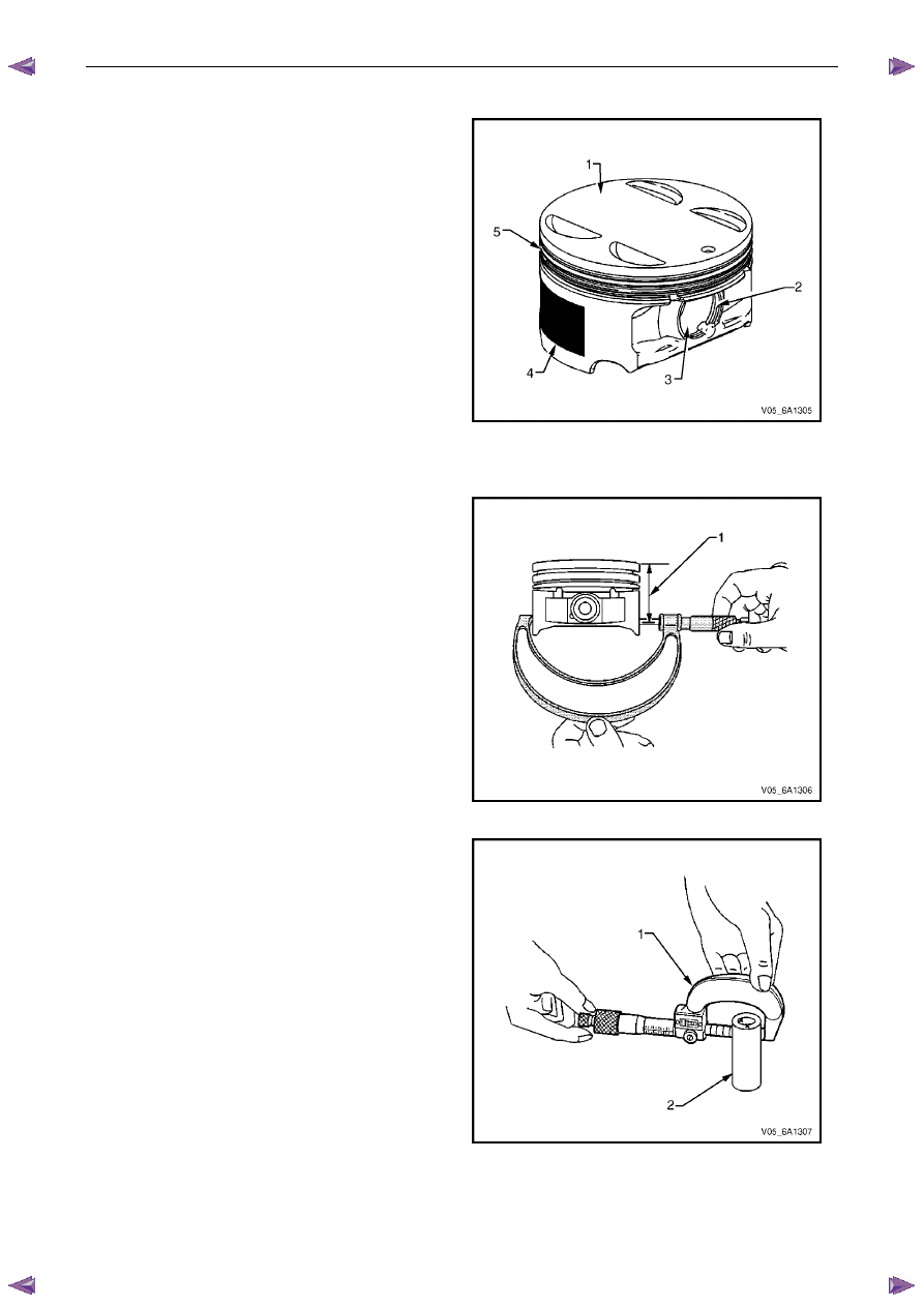
Piston Inspection Procedure 

Inspect the pistons for the following conditions: 
• 

eroded areas at the top of the piston (1), 

• 

piston pin retainer grooves for burrs (2), 

• 

worn piston pin bores or worn piston pins (3), 

• 

scuffed or damaged skirt coating (4), 

• 

ring grooves for cracks, nicks or burrs that may 
cause binding (5), and 

• 

warped or worn ring lands. 

Replace pistons that show any signs of damage or 
excessive wear. 

Figure 6A1 – 384 

Piston Measurement 

Measure piston width using the following procedure:

Using an outside micrometer, measure the 
width of the piston at 30 mm below the crown 
top (1), at the thrust surfaces of the piston, 
perpendicular to the piston pin centreline. 

Compare the measurement of the piston to its 
original cylinder by subtracting the piston width 
from the cylinder diameter. 

Check your measurements with specifications, 
refer to 5 

Specifications. 

If the clearance obtained through measurement 
is greater than the provided specifications and 
the cylinder bores are within specification, 
replace the piston. 

Figure 6A1 – 385 

Measure the piston pin bore to piston pin (2) 
clearances using the following procedure: 

Piston pin bores and pins must be free of 
varnish or scuffing. 

Use an outside micrometer (1) to measure the 
piston pin in the piston contact areas. 

Figure 6A1 – 386 

Engine Mechanical – V6 

Page 6A1–214 


Using an inside micrometer, measure the piston pin 
bore (1). Compare the result with the piston pin 
diameter and piston pin to piston pin bore clearance 
listed in the specifications, refer to 5 

Specifications.

If the clearance is excessive, determine which piece 
is out of specification and replace as required. 

Replace the piston if any of its dimensions are out of 
specification. 

If the new piston does not meet clearance 
specifications, the cylinder block may need to be 
oversized to 0.25 mm. There is only one size of 
oversized pistons and rings available for service. 

Figure 6A1 – 387 

Piston Ring Measurement 

Measure the piston ring end gap using the following 
procedure: 

Place the piston ring (1) in the area of the bore where 
the piston ring will travel, approximately 25 mm below 
the deck surface. Ensure the ring is square with the 
cylinder bore by positioning the ring with the piston 
head. 

Measure the end gap of the piston ring with feeler 
gauges (2), refer to 5 Specifications. 

If the clearance exceeds the provided specifications, 
the piston rings must be replaced. 

Repeat the procedure for all piston rings. 

Figure 6A1 – 388 

Measure the piston ring side clearance using the 
following procedure: 

Roll the piston ring (1) entirely around the piston ring 
groove. If any binding is caused by the ring groove, 
dress the groove with a fine file. If any binding is 
caused by a distorted piston ring, replace the ring. 

With the piston ring on the piston, use feeler 
gauges (2) to check clearance at multiple locations. 

Compare the measurements with piston ring side 
clearance listed in the specifications, refer to 5
 Specifications. 

If the clearance is greater than specifications, replace 
the piston rings. 

Figure 6A1 – 389 

Engine Mechanical – V6 

Page 6A1–215 


There is a locating dimple (1) on the compression 
rings. Install the compression rings with the dimple 
facing up. 

If the new ring does not reduce the clearance to the 
correct specification, install a new piston. 

If the new piston does not meet clearance 
specifications, the cylinder block may need to be 
oversized to 0.25 mm. There is only one size of 
oversized pistons and rings available for service. 

Figure 6A1 – 390 


Connecting Rod Cleaning Procedure 

Clean the connecting rods in solvent. 


Safety glasses must be worn when using 
compressed air. 

Dry the connecting rod using compressed air. 

Remove the connecting rod cap and clean the threads. 

Remove the connecting rod bearing and discard. Never reuse a connecting rod bearing that has been used in a 
running engine. 

Connecting Rod Visual Inspection Procedure 

Inspect the piston pin bushing (4) for scoring or 
damage. 

Inspect the connecting rod beam (1) for twisting or 
bending. 

Inspect the rod cap (2) for any nicks or damage 
caused by possible interference. 

Inspect for scratches or abrasion on the rod bearing 
seating surface. 

If the connecting rod bores contain minor scratches or 
abrasions, clean the bores in a circular direction with 
a light emery paper. 

Retain the original bolts (3) for preliminary assembly. 
They must be replaced for final assembly. 

Figure 6A1 – 391 

Engine Mechanical – V6 

Page 6A1–216 


Connecting Rod Measurement Procedure 

Piston Pin End 

N O T E  

Measurements of all components should be 
taken with the components at normal room 
temperature. 

Using an outside micrometer (1), take two 
measurements of the piston pin (2) in the area of the 
connecting rod contact. 

Figure 6A1 – 392 

Using an inside micrometer, measure the connecting 
rod piston pin bore (1). 

Subtract the piston pin diameter from the piston pin 
bore. 

Compare the clearance measurements listed in the 
specifications, refer to 5 

Specifications. 

If the clearance is excessive, replace the piston pin. If 
a new pin does not resolve the clearance problem, 
replace the connecting rod. 

Figure 6A1 – 393 

Crankshaft Bearing End 

N O T E  

Measurements of all components should be 
taken with the components at normal room 
temperature. 

Using an inside micrometer, measure the connecting 
rod crankshaft bearing bore (1). 

Compare the bore measurements listed in the 
specifications, refer to 5 

Specifications. 

Replace the connecting rod if the bore is out of 
specification. Do not recondition the connecting rod.

Figure 6A1 – 394 


Content   ..  671  672  673  674   ..