Isuzu KB P190. Manual - part 655
Engine Mechanical – V6
Page 6A1–141
Reassemble
CAUTION
As there are no serviceable components
within the oil pump, a disassembled oil pump
must be replaced.
Reinstall
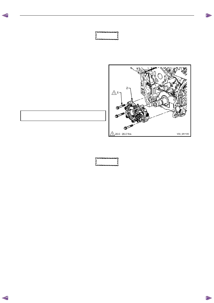
1
Align the oil pump gerotor with the crankshaft flats
and fit the oil pump assembly to the engine block.
2
Align the pump body (2) with the mounting holes in
the cylinder block.
3
Install the oil pump bolt (1), three places, and tighten
to the correct torque specification.
4
Install the primary timing chain, refer to 3.16
Timing Chains, Tensioners, Shoes and Guides.
Oil pump attaching bolt torque
specification ............................................20.0 – 26.0 Nm
Figure 6A1 – 223
3.18 Camshaft
Sprocket
CAUTION
Setting the camshaft timing is required
whenever the camshaft drive system is
disturbed to ensure the relationship between
any chain and sprocket is not lost. Even when
only one sprocket is involved, multiple
crankshaft rotations will not produce
conditions where correct timing can be
confirmed.
If required, follow the Left-hand Secondary
Camshaft Chain Components reinstallation
procedure to reset the camshaft timing.
Remove
Right-hand Side
1
Remove the right-hand camshaft cover, refer to 3.12
Camshaft Cover.
2
Remove the camshaft position sensors, refer to 6C1-3 Engine Management – Service Operations.
3
Remove the camshaft position actuator solenoids, refer to 6C1-3 Engine Management – V6 – Service Operations.
4
Remove the crankshaft balancer assembly, refer to 3.13 Crankshaft Balancer Assembly.