Isuzu KB P190. Manual - part 606


  Index      Isuzu     Isuzu KB P190 - service repair manual 2007 year


Search            


Content   ..  604  605  606  607   ..


Isuzu KB P190. Manual - part 606


6E–254

ENGINE DRIVEABILITY AND EMISSIONS

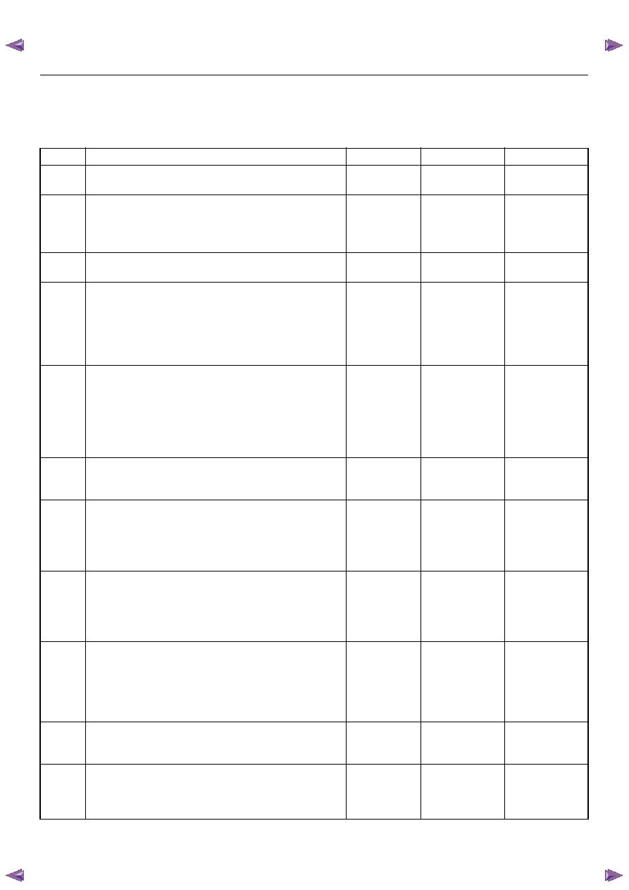
DETONATION/SPARK KNOCK SYMPTOM

DEFINITIONS: A mild to severe ping, usually worse under acceleration. The engine makes a sharp metallic knocking
sound that changes with throttle opening. Prolonged detonation may lead to complete engine tailure.

Step

Action

Value(s)

Yes

No

1

Was the “On-Board Diagnostic (OBD) System Check
performed?

Go to Step 2

Go to OBD 

System Check

2

1. Perform a bulletin search.

2. If a bulletin that addresses the symptom is found,

correct the condition as instructed in the bulletin.

Was a bulletin found that addresses the symptom?

Verify repair

Go to Step 3

3

Was a visual/physical check performed?

Go  to  Step 4

Go to Visual / 

physical Check.

4

1. If Tech 2 readings are normal (refer to Typical

Scan Data Values) and there are no engine
mechanical faults, fill the fuel tank with a known
quality gasoline.

2. Re-evaluate the vehicle performance.

Is detonation present?

Go to Step 5

Verify repair

5

1. Check for obvious overheating problems:

• Low engine coolant

• Restricted air flow to radiator

• Incorrect coolant solution

2. If a problem is found, repair as necessary.

Was a problem found?

Verify repair

Go to Step 6

6

Check the fuel pressure. Refer to 6E-108 page “Fuel
System Diagnosis” 
.
Was a problem found?

Verify repair

Go to Step 7

7

1. Using a Tech 2, display the MAP sensor value in

comparison with atmosphere temperature.

2. Check for a faulty, plugged, or incorrectly installed

MAP sensor.

Was the problem found?

Verify repair

Go to Step 8

8

1. Using a Tech 2, display the ECT sensor and IAT

sensor value and warm up condition compared
with the typical data.

2. Check the specified value or wire.

Was the problem found?

Verify repair

Go to Step 9

9

Observe the throttle position display on the Tech 2
while slowly increasing throttle pedal.
Does the throttle position increase steady with
increasing smoothly?

Go  to  Step 10

Refer to 

Diagnostic 

Trouble Code 

P0123 for 

further 

diagnosis

10

Check the knock sensor wire, shield wire, or
installation condition.
Was a problem found?

Verify repair

Go to Step 11

11

Check items that can cause the engine to run lean.
Refer to DTC P1171 “Fuel Supply System Lean
During Power Enrichment”.
Was a problem found?

Verify repair

Go to Step 12

ENGINE DRIVEABILITY AND EMISSIONS

6E–255

12

Check spark plugs for proper heat range.
Were incorrect spark plugs installed?

Verify repair

Go to Step 13

13

1. Remove excessive carbon buildup with a top

engine cleaner.

2. Re-evaluate vehicle performance.

Is detonation still present?

Verify repair

Go to Step 14

14

Check for an engine mechanical problem. Perform a
cylinder compression check. Refer to Engine
Mechanical
.
Was a problem found?

Verify repair

Go to Step 15

15

1. Review all diagnostic procedures within this table.

2. If all procedures have been completed and no

malfunctions have been found, review/inspect the
following:

• Visual/physical inspection

• Tech 2 data

• All electrical connections within a suspected

circuit and/or system

Was a problem found?

Verify repair

Go to Step 16

16

Is the ECM programmed with the latest software
release? 
If not, download the latest software to the ECM using
the “SPS (Service Programming System)”. 
Was the problem solved?

Verify repair

Go to Step 17

17

Replace the ECM. 
Is the action complete? 
IMPORTANT:  The replacement ECM must be
programmed. Refer to section of the Service
Programming System (SPS) in this manual. 
Following ECM programming, the immobilizer system
(if equipped) must be linked to the ECM. Refer to
section 11 “Immobilizer System-ECM replacement” for
the ECM/Immobilizer linking procedure.

Verify Repair

Step

Action

Value(s)

Yes

No

6E–256

ENGINE DRIVEABILITY AND EMISSIONS

POOR FUEL ECONOMY SYMPTOM

DEFINITIONS: Fuel economy, as measured by an actual road test, is noticeably lower than expected. Also, economy
is noticeably lower than it was on this vehicle at one time, as previously shown by an actual road test.

Step

Action

Value(s)

Yes

No

1

Was the “On-Board Diagnostic (OBD) System Check
performed?

Go to Step 2

Go to OBD 

System Check

2

1. Perform a bulletin search.

2. If a bulletin that addresses the symptom is found,

correct the condition as instructed in the bulletin.

Was a bulletin found that addresses the symptom?

Verify repair

Go to Step 3

3

Was a visual/physical check performed?

Go  to  Step 4

Go to Visual / 

physical Check.

4

Check owner’s driving habits.

• Is the A/C On full time (defroster mode On)?

• Are tires at the correct pressure?

• Are excessively heavy loads being carried?

• Is acceleration too much, too often?

Go to Step 5

Go to Step 6

5

Review the items in Step 4 with the customer and
advise as necessary.
Is the action complete?

System OK

6

Visually/physically check: Vacuum hoses for splits,
kinks, and improper connections and routing as
shown on the “Emission Control System Schematics”.
Was a problem found?

Verify repair

Go to Step 7

7

Check for low engine coolant level.
Was a problem found? 

Verify repair

Go to Step 8

8

Check for incorrect or faulty engine thermostat. Refer
to Engine Cooling.
Was a problem found?

Verify repair

Go to Step 9

9

Remove and check the air filter element for dirt or for
restrictions.
Was a problem found?

Verify repair

Go to Step 10

10

1. Using a Tech 2, display the MAP sensor value in

comparison with atmosphere temperature.

2. Check for a faulty, plugged, or incorrectly installed

MAP sensor.

Was the problem found?

Verify repair

Go to Step 11

11

1. Using a Tech 2, display the ECT sensor and IAT

sensor value and warm up condition compared
with the typical data.

2. Check the specified value or wire.

Was the problem found?

Verify repair

Go to Step 12

12

Check the knock sensor wire, shield wire, or
installation condition.
Was a problem found?

Verify repair

Go to Step 13

13

Check the fuel pressure. Refer to 6E-108 page“Fuel
System Diagnosis

” 

.

Was a problem found?

Verify repair

Go to Step 14

ENGINE DRIVEABILITY AND EMISSIONS

6E–257

14

Monitor “B1S1 (Bank 1 Sensor 1) Status” on the Tech
2.
Is the “B1S1 (Bank 1 Sensor 1) Status” in the rich
condition?

Verify repair

Go to Step 15

15

Check items that can cause the engine to run rich.
Refer to DTC P1167 “Fuel Supply System Rich During
Deceleration Fuel Cut Off”.
Was a problem found?

Verify repair

Go to Step 16

16

1. Remove the spark plugs and check for gas or oil

fouling cracks, wear, improper gap, burned
electrodes, heavy deposits, or improper heat
range.

2. If spark plugs are fouled, the cause of fouling must

be determined before replacing the spark plugs.

Was a problem found?

Verify repair

Go to Step 17

17

Check for proper calibration of the speedometer.
Does the speed indicated on the speed meter closely
match the vehicle speed displayed on the Tech 2?

Go to Step 19

Go to Step 18

18

Diagnose and repair the inaccurate speedometer
condition as necessary. Refer to Vehicle Speed
Sensor in Electrical Diagnosis
.

Verify Repair

19

Check for proper calibration of the fuel gauge.
Was a problem found?

Verify repair

Go to Step 20

20

Check for the following engine mechanical problems
(refer to Engine Mechanical):

• Low compression

• Worn camshaft

• Sticking or leaking valves

• Valve timing
Was a problem found?

Verify repair

Go to Step 21

21

1. Review all diagnostic procedures within this table.

2. If all procedures have been completed and no

malfunctions have been found, review/inspect the
following:

• Visual/physical inspection

• Tech 2 data

• All electrical connections within a suspected

circuit and/or system

Was a problem found?

Verify repair

Go to Step 22

22

Is the ECM programmed with the latest software
release? 
If not, download the latest software to the ECM using
the “SPS (Service Programming System)”. 
Was the problem solved?

Verify repair

Go to Step 23

23

Replace the ECM. 
Is the action complete? 
IMPORTANT:  The replacement ECM must be
programmed. Refer to section of the Service
Programming System (SPS) in this manual. 
Following ECM programming, the immobilizer system
(if equipped) must be linked to the ECM. Refer to
section 11 “Immobilizer System-ECM replacement” for
the ECM/Immobilizer linking procedure.

Verify Repair

Step

Action

Value(s)

Yes

No


Content   ..  604  605  606  607   ..