Isuzu KB P190. Manual - part 578


  Index      Isuzu     Isuzu KB P190 - service repair manual 2007 year


Search            


Content   ..  576  577  578  579   ..


Isuzu KB P190. Manual - part 578


6E–142

ENGINE DRIVEABILITY AND EMISSIONS

11

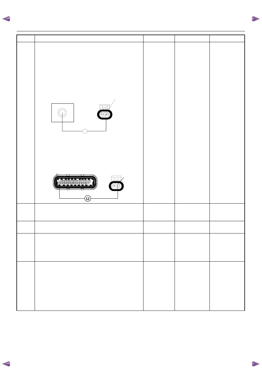
Using the DVM and check the ECT sensor ground
circuit.
Breaker box is available: 

1. Ignition “Off”, engine “Off”. 

2. Install the breaker box as type A. (ECM

disconnected) Refer to 6E-88 page.

3. Disconnect the ECT sensor connector. 

4. Check the circuit for open circuit. 

Was the problem found?

Breaker box is not available: 

1. Ignition “Off”, engine “Off”. 

2. Disconnect the ECT sensor connector. 

3. Check the circuit for open circuit. 

Was the problem found?

Repair faulty 

harness and 

verify repair

Go to Step 14

12

Substitute a known good ECT sensor assembly and
recheck. 
Was the problem solved?

Go to Step 13

Go to Step 14

13

Replace the ECT sensor. 
Is the action complete?

Verify repair

14

Is the ECM programmed with the latest software
release? 
If not, download the latest software to the ECM using
the “SPS (Service Programming System)”. 
Was the problem solved?

Verify repair

Go to Step 15

15

Replace the ECM. 
Is the action complete? 
IMPORTANT:  The replacement ECM must be
programmed. Refer to section of the Service
Programming System (SPS) in this manual. 
Following ECM programming, the immobilizer system
(if equipped) must be linked to the ECM. Refer to
section 11 “Immobilizer System-ECM replacement” for
the ECM/Immobilizer linking procedure.

Verify repair

Step

Action

Value(s)

Yes

No

J1-32

Breaker Box

Ω

E-69

2

2

32

E60(J1)

E69

ENGINE DRIVEABILITY AND EMISSIONS

6E–143

DIAGNOSTIC TROUBLE CODE (DTC) P0122 THROTTLE POSITION SENSOR 

LOW INPUT

Condition for setting the DTC and action taken when the DTC sets

Circuit Description

The throttle position sensor circuit provides a signal
voltage that changes relative to throttle blade angle. The
signal voltage will vary from below 1 volt at closed
throttle to about 4 volts at wide open throttle (WOT).
The TPS signal is used by the engine control module
(ECM) for fuel control and most of the ECM-controlled
outputs. If the ECM detect a continuous short to ground
in the TPS or circuit, then a code P0122 will set.

Diagnostic Aids

• Poor connection at ECM - Inspect harness

connectors for backed-out terminals, improper
mating, broken locks, improperly formed or damaged
terminals, and poor terminal-to-wire connection.

• Damaged harness - Inspect the wiring harness for

damage, short to ground, short to battery positive,
and open circuit. If the harness appears to be OK,
observe the throttle position display on the Tech 2
while moving connectors and wiring harnesses
related to the TPS. A change in the display will
indicate the location of the fault.

Code

Type

DTC Name

DTC Setting Condition

Fail-Safe (Back Up)

P0122

A

Throttle Position Sensor Low Input

TPS output voltage is below 0.14V.

The ECM uses 0% condition as substitute.

6E–144

ENGINE DRIVEABILITY AND EMISSIONS

Diagnostic Trouble Code (DTC) P0122 Throttle Position Sensor Low Input

Step

Action

Value(s)

Yes

No

1

Was the “On-Board Diagnostic (OBD) System Check”
performed?

Go  to  Step 2

Go to On Board 

Diagnostic 

(OBD) System 

Check

2

1. Connect the Tech 2. 

2. Review and record the failure information. 

3. Select “F0: Read DTC Infor By Priority” in “F0:

Diagnostic Trouble Code”. 

Is the DTC P0122 stored as “Present Failure”?

Go to Step 3

Refer to 

Diagnostic Aids 

and Go to Step 

3

3

1. Using the Tech2, ignition “On” and engine “Off”. 

2. Select “Clear DTC Information” with the Tech2 and

clear the DTC information. 

3. Operate the vehicle and monitor the “F5: Failed

This Ignition” in “F2: DTC Information”.

Was the DTC P0122 stored in this ignition cycle?

Go to Step 4

Refer to 

Diagnostic Aids 

and Go to Step 

4

4

Check for poor/faulty connection at the TPS or ECM
connector. If a poor/faulty connection is found, repair
as necessary. 
Was the problem found?

Verify repair

Go to Step 5

5

Visually check the TPS. 
Was the problem found? 

Go to Step 10

Go to Step 6

6

Using the DVM and check the TPS.

1. Ignition “Off”,  engine “Off”. 

2. Disconnect TPS connector. 

3. Measure the resistance of TPS. 

Does the tester indicate standard resistance as shown
in the following table? 

Standard 

resistance

Go to Step 7

Go to Step 10

E60(J1)

E68

32

15 7

Measurement 

Terminal

Resistance (

Ω)

1 - 2

Approximately 5.6k

Ω at idle position & 

WOT

2 - 3

Approximately 6.0k

Ω at idle position

Approximately 1.7k

Ω at WOT

1 - 3

Approximately 2.3k

Ω at idle position & 

WOT

Approximately 6.6k

Ω at WOT

2

1

3

TPS

ENGINE DRIVEABILITY AND EMISSIONS

6E–145

7

Using the DVM and check the TPS power supply
circuit.

1. Ignition “On”, engine “Off”. 

2. Disconnect the TPS connector. 

3. Check the circuit for open or short to ground

circuit. 

Was the DVM indicated specified value?

Approximately 

5.0V

Go to Step 9

Go to Step 8

8

Repair the open or short to ground circuit between the
ECM and TPS. 
Was the problem solved?

Verify repair

Go to Step 12

Step

Action

Value(s)

Yes

No

V

E68

2

2

E60(J1)

E68

15


Content   ..  576  577  578  579   ..