Isuzu KB P190. Manual - part 513


  Index      Isuzu     Isuzu KB P190 - service repair manual 2007 year


Search            


Content   ..  511  512  513  514   ..


Isuzu KB P190. Manual - part 513


6A-38 ENGINE MECHANICAL (C24SE) 


Inspection 

All parts, if necessary replace. 


When replacing camshaft, always replace all cam followers. 
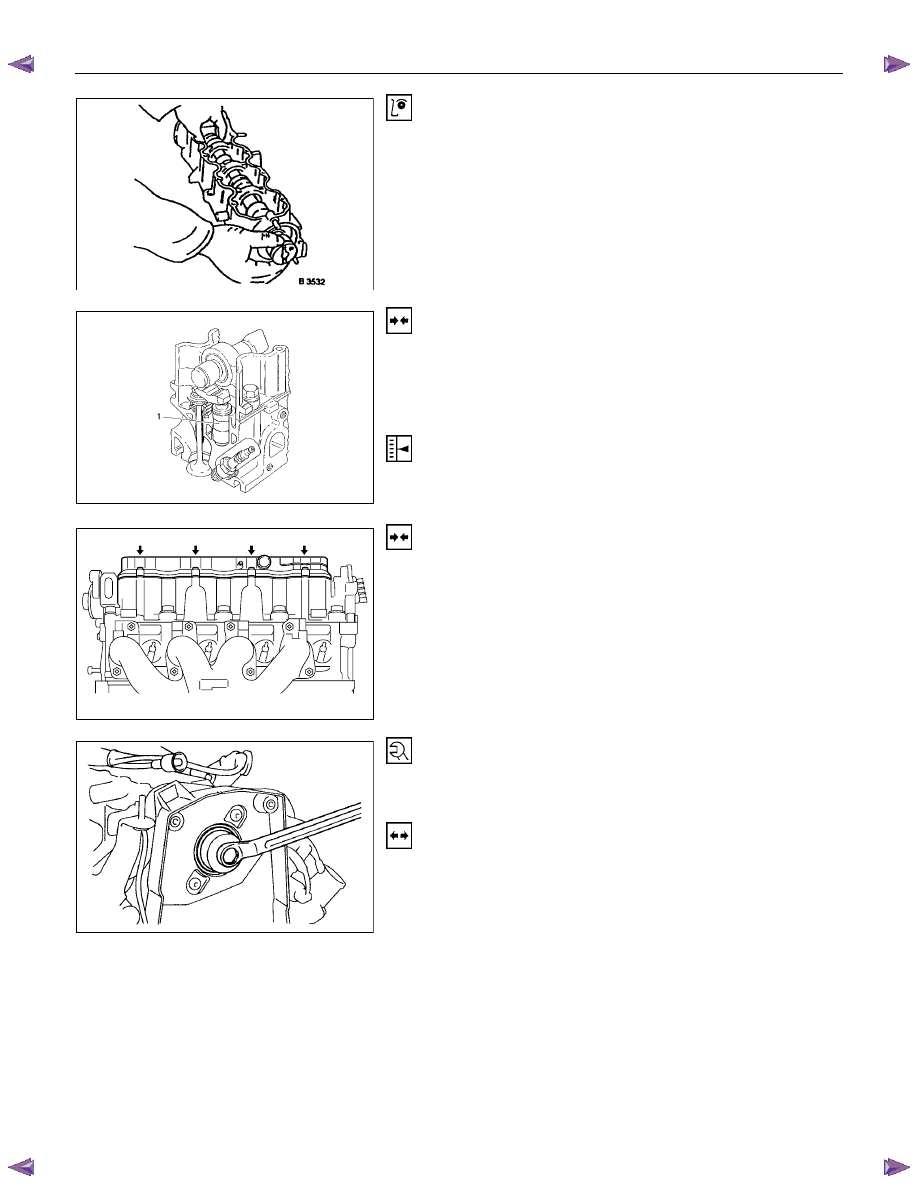


Installation 

Insert hydraulic valve lifter (1) in camshaft housing. 


Coat sliding surfaces of rocker arm with Mcs, Paste and insert 

in camshaft housing. 


Adjust 

Adjustment of the hydraulic valve liters is not required. 

Pretension is provided by the design. 


Installation 

  1.  Remove 5-8840-0457-0 and install the camshaft housing 

cover. 

  2.  Insert the spark plug connectors. 


Tighten (Torque) 

Guide plate to camshaft housing. 

Insert camshaft with MoS

2

 paste. 


Installation 

  1.  Install the front seal ring in camshaft housing with  

5-8840-0451-0. 

  2.  Install the camshaft housing rear cover. 

  3.  Install the cylinder head. 

ENGINE MECHANICAL (C24SE) 6A-39 


Camshaft Housing, Check for Plane Surface 

Clean 

Sealing surfaces. 
 

Inspection 

Check length and width of sealing surface for deformation and 
diagnosis for warpage and use straight edge feeler gauge. 
 

Measure 

Height of camshaft housing (sealing surface to sealing 
surface). 
Dimension I: (74.0 mm) 


Cylinder Head, Removal and Installation 

Important 

Only remove cylinder head with engine cold (room 
temperature). 


Removal 

  1.  Remove the alternator, power steering and V-belts. 


Removal 

  2.  Loosen the fastening bolts from alternator. 

  3.  Loosen the lower alternator fastening bolt by swinging 

the alternator to the rear. 


Removal 

  4.  Remove the front toothed belt cover. 

  5.  Remove the toothed belt from camshaft pulley. 


See operation "Timing Check and Adjust". 


6A-40 ENGINE MECHANICAL (C24SE) 


Removal 

  6.  Remove the camshaft housing cover and camshaft 

pulley by counter-holding at the hex head of camshaft. 


Removal 

  7.  Remove the fastening bolts from camshaft housing. 


Removal 

  8.  Remove the exhaust pipe from exhaust manifold. 

  9.  Loosen the cylinder head bolts spirally from the outside 

inwards (first 1/4, then 1/2 revolution). 


Removal 

  1.  Remove the camshaft housing from cylinder head. 

  2.  Remove the cam followers, thrust pieces and hydraulic 

valve lifters. 


Note the allocation. 

  3.  Remove the cylinder head. 


Clean 

Sealing surfaces, bores and threads of cylinder head bolts. 
 

Inspection 

Check cylinder head and cylinder block for plane surfface-see 
operations “Cylinder Head, Check for Plane Surface” and 
“Cylinder Block, Check for Plane Surface.” 
 

ENGINE MECHANICAL (C24SE) 6A-41 


Installation 

  1.  Install the cylinder head gasket. 


Mark "OBEN/TOP" on top and turn it towards timing side 
of engine. 

  2.  Place cylinder head on cylinder block. 


1
2
3


Installation 

  1.  Insert the hydraulic valve lifters (3), thrust pieces (2) and 

cam followers (1) with MoS2 paste. 

   Note 

allocation. 

  2.  Apply a bead of Sealing Compound TB1207C to sealing 

surface of cylinder head. 

  3.  Install the camshaft housing on cylinder head. 


Torque-Angle Method 

Cylinder head and camshaft housing with new cylinder head 
bolts to cylinder block. 
 
Cylinder head bolts in sequence shown. 


Installation 

  1.  Install the rear toothed belt cover to camshaft housing. 

  2.  Install the camshaft pulley to camshaft. 

  3.  Install the camshaft housing cover to housing. 


Installation 

  1.  Install the toothed belt on camshaft pulley. 


See operation "Timing  Adjust". 

  2.  Install the front toothed belt cover. 


Content   ..  511  512  513  514   ..