Isuzu KB P190. Manual - part 503


  Index      Isuzu     Isuzu KB P190 - service repair manual 2007 year


Search            


Content   ..  501  502  503  504   ..


Isuzu KB P190. Manual - part 503


6-12 ENGINE DIAGNOSIS (C24SE) 

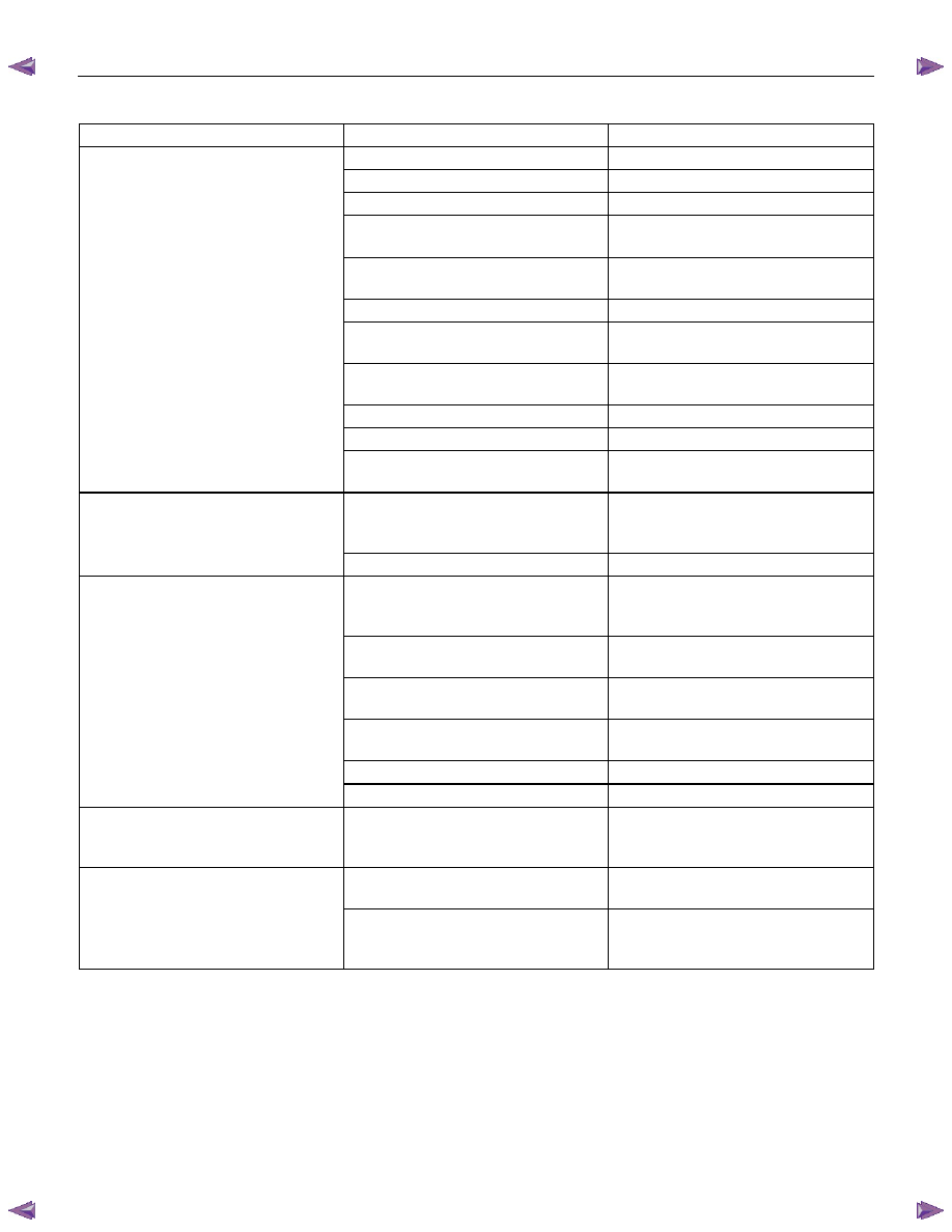
Engine Oil Consumption Excessive  

Condition Possible 

cause Correction 

Oil leaking 

Oil pan drain plug loose 

Retighten or replace gasket 


Oil pan setting bolds loosened 

Retighten 


Oil pan gasket broken 

Replace gasket 


Front cover retaining bolts loose 
or gasket broken 

Retighten or replace gasket 


Head cover retaining bolts loose 
or gasket broken 

Retighten or replace gasket 


Oil filter adapter cracked 

Replace 


Oil filter attaching bolt loose or 
rubber gasket broken 

Retighten or replace oil filter 


Crankshaft front or rear oil seal 
defective 

Replace oil seal 


Oil pressure unit loose or broken 

Retighten or replace 


Blow-by gas hose broken 

Replace hose 

 Engine/Transmission 

coupling 

area 

Replace oil seal 

Oil leaking into combustion 
chambers due to poor seal in 
valve system 

Valve stem oil seal defective 

Replace 


Valve stem or valve guide worn 

Replace valve and valve guide 

Oil leaking into combustion 
chambers due to poor seal in 
cylinder parts 

Cylinders and pistons worn 
excessively 

Rebore cylinder and replace 
pistons and others 


Piston ring gaps incorrectly 
positioned 

Correct 


Piston rings set with wrong side 
up 

Correct 


Piston rings sticking 

Rebore cylinder and replace 
pistons and others 


Piston ring and ring groove worn 

Replace pistons and others 


Return ports in oil rings clogged 

Clean piston and replace rings 

Crank case ventilation, Positive 
Crankcase Ventilation System 
malfunctioning 

Positive Crankcase Ventilation 
Hose clogged 

Clean 

Others 

Improper oil viscosity 

Use oil of recommended S.A.E. 
viscosity 


Continuous high speed driving 
and or severe usage such as 
trailer towing 

Continuous high speed operation 
and or severe usage will normally 
cause increased oil consumption 


ENGINE DIAGNOSIS (C24SE) 6-13 

Fuel Consumption Excessive 

Condition Possible 

cause Correction 

Trouble in fuel system 

Mixture too rich or too lean due to 
trouble in fuel injection system 

Refer to "Abnormal Combustion" 


Fuel cut function does not act 

Refer to "Abnormal Combustion" 

Trouble in ignition system 

Misfiring or abnormal combustion 
due to trouble in ignition system 

Refer to Hard Start or Abnormal 
Combustion Troubleshooting 
Guide 

Others 

Engine idle speed too high 

Reset Idle Air Control Valve 


Returning of accelerator control 
sluggish 

Correct 


Fuel system leakage 

Correct or replace 

 Clutch 

slipping 

Correct 

 Brake 

drag 

Correct 


Selection of transmission gear 
incorrect 

Caution operator of incorrect gear 
selection 

Oil Problems 

Condition Possible 

cause Correction 

Oil pressure too low 

Wrong oil in use 

Replace with correct engine oil 


Relief valve sticking 

Replace 


Oil pump not operating properly 

Correct or replace 


Oil pump strainer clogged 

Clean or replace strainer 


Oil pump worn 

Replace 


Oil pressure gauge defective 

Correct or replace 


Crankshaft bearing or connecting 
rod bearing worn 

Replace 

Oil contamination 

Wrong oil in use 

Replace with new engine oil 


Oil filter clogged 

Replace oil filter 


Cylinder head gasket damage 

Replace gasket 


Burned gases leaking 

Replace piston and piston rings or 
rebore cylinders 

Oil not reaching valve system 

Oil passage in cylinder head or 
cylinder body clogged 

Clean or correct 


Engine Oil Pressure Check 

  1.  Check for dirt, gasoline or water in the engine 

oil. 

a.  Check the viscosity of the oil. 
b.  Change the oil if the viscosity is outside the 

specified standard. 

c.  Refer to the "Maintenance and Lubrication" 

section of this manual. 

  2.  Check the engine oil level. 

The level should fall somewhere between the 
"ADD" and the "FULL" marks on the oil level 
dipstick. 
If the oil level does not reach the "ADD" mark on 
the oil level dipstick, engine oil must be added. 


  3.  Remove the oil pressure unit. 

  4.  Install an oil pressure gauge. 

  5.  Start the engine and allow the engine to reach 

normal operating temperature (About 80

°C). 

  6.  Measure the oil pressure. 


Oil pressure should be: 


150 kPa(21.8 psi) at idle speed. 

  7.  Stop the engine. 

  8.  Remove the oil pressure gauge 

  9.  Install the oil pressure unit. 

 10.  Start the engine and check for leaks. 

6-14 ENGINE DIAGNOSIS (C24SE) 

Malfunction Indicator Lamp  

The instrument panel "CHECK ENGINE" Malfunction 

Indicator lamp (MIL) illuminates by self diagnostic 

system when the system checks the starting of 

engine, or senses malfunctions. 


Condition Possible 

cause Correction 

"CHECK ENGINE" MIL does not 
illuminate at the starting of engine 

Bulb defective 

Replace 


MIL circuit open 

Correct or replace 


Command signal circuit to operate 
self diagnostic system shorted 

Correct or replace 


Engine Control Module (ECM) 
cable loosely connected, 
disconnected or defective 

Correct or replace 

 ECM 

defective 

Replace 

“CHECK ENGINE” MIL 
illuminates, and stays on 

Deterioration heated oxygen 
sensor of internal element 

Replace 


Heated oxygen sensor connector 
terminal improper contact  

(If applicable) 

Reconnect properly 


Heated oxygen sensor lead wire 
shorted (If applicable) 

Correct 


Heated oxygen sensor circuit 
open (If applicable) 

Correct or replace 


Deterioration engine coolant 
temperature sensor of internal 
element 

Replace  


Engine coolant temperature 
sensor connector terminal 
improper contact 

Reconnect properly 


Engine coolant temperature 
sensor lead wire shorted 

Correct 


Engine coolant temperature 
sensor circuit open 

Correct or replace 


Throttle position sensor open or 
shorted circuits 

Correct or replace 


Deterioration of crankshaft 
position sensor 

Replace 


Crankshaft position sensor circuit 
open or shorted 

Correct or replace 


Vehicle speed sensor circuit open 

Correct or replace 


Manifold absolute pressure sensor 
circuit open or shorted 

Correct or replace 


Intake air temperature sensor 
circuit open or shorted 

Correct or replace 


Fuel injector circuit open or shorted

Correct or replace 


ECM driver transistor defective 

Replace EPROM or ECM 


Malfunctioning of ECM RAM 
(Random Access Memory) or 
Malfunctioning of ECM PROM 
(Programmed Read Only Memory)

Replace EPROM or ECM 


ENGINE MECHANICAL (C24SE) 6A-1 

SECTION 6A 

ENGINE MECHANICAL 

TABLE OF CONTENTS 

PAGE 

General Description ........................................................................................................   6A- 4 

ENGINE PICTORIAL....................................................................................................   6A-  6 

Main Data and Specification...........................................................................................   6A-11 

CRANKCASE VENTILATION SYSTEM.......................................................................   6A-16 

ENGINE ASSEMBLY & LOOSE PARTS .....................................................................   6A-17 

OPERATIONS ON ENGINE AGGREGATES....................................................................   6A-18 

Engine Damping Blocks(Engine without Transmission) ........................................   6A-18 

Toothed Belt and Timing Check  ...............................................................................   6A-21 

Toothed Belt Tension, Adjust ....................................................................................   6A-23 

Toothed Belt, Replace ................................................................................................   6A-24 

OPERATIONS ON INSTALLED ENGINE.........................................................................   6A-26 

Gasket, Exhaust Manifold, Cylinder Head ................................................................   6A-26 

Gasket, Intake Manifold, Cylinder Head....................................................................   6A-26 

Seal Ring, Camshaft Housing, Timing Side..............................................................   6A-27 

Seal Ring, Thermostat Housing, Cylinder Head.......................................................   6A-27 

Seal Ring - Front Camshaft Housing, Replace.........................................................   6A-28 

Toother Belt Rear Cover.............................................................................................   6A-30 

Toother Belt Tension Roller.......................................................................................   6A-31 

COMPONENT PARTS ......................................................................................................   6A-32 

Cylinder Head..............................................................................................................   6A-32 

Hydraulic Valve Lifter .................................................................................................   6A-33 

OPERATIONS ON CYLINDER HEAD AND CAMSHAFT HOUSING ...............................   6A-34 

Camshaft .....................................................................................................................  6A-34 

Camshaft Housing Removal and Installation ...........................................................   6A-35 

Cylinder Head..............................................................................................................   6A-35 

Hydraulic Valve Lifers, Replace.................................................................................   6A-37 

Camshaft Housing, Replace ......................................................................................   6A-37 


Content   ..  501  502  503  504   ..