Isuzu KB P190. Manual - part 389


  Index      Isuzu     Isuzu KB P190 - service repair manual 2007 year


Search            


Content   ..  387  388  389  390   ..


Isuzu KB P190. Manual - part 389


FUEL SYSTEM (4JK1/4JJ1)  6C-15 

The fuel system consists of many tiny holes and spaces
that allow the movement of fuel from one place to
another. These holes and spaces are milled to
extremely high precision. This is especially true of the
fuel injector. 

The fuel injector is very sensitive to foreign material.
Foreign material will result in fuel system breakdown.
Exercise great care not to allow the entry of foreign
material into the fuel system or fuel injector during the
removal and installation procedure. 

Note: To avoid electric shock;    
Set the switch to the 'OFF' position and disconnect the 
negative battery cable before checking or repairing the
fuel injector, wiring or/and connectors. 

Removal 

1.  Remove the cylinder head cover. 

  Refer to the removal procedure for the cylinder 

head cover in this manual. 

Remove the attachment bolt of the engine oil gauge 
guide tube. 

2. Loosen the fuel injector clamp fixing bolts and

remove the fuel injector. 


If the fuel injector is difficult to remove, use the

remover. Use a screwdriver to force the fuel

injector clamp off the fuel injector. 

Note: Do not remove the fuel injector sleeve. 

Note: Cover the areas exposed during parts removal to
prevent the entry of foreign material into the fuel
system. 

3. Mark each fuel injector with the number of the

cylinder from which it was removed. Store the fuel

injector in a safe place. Position the fuel injector so

that the nozzle is protected. 


Note: Do not tamper with the electromagnetic portion of
the fuel injector. Reduced electromagnetic function will
result in injector failure. 

Note: After replacement of the fuel injector, perform the 
following procedure. 

•  All fuel injectors are replaced:  
  Remove the fuel injector ID code label on the

cylinder head cover. 

•  Any fuel injector(s) is replaced:  
 

Black out the replaced cylinder of the fuel injector

ID code on the fuel injector ID code label with a

marking pen or equivalent. 


Installation 

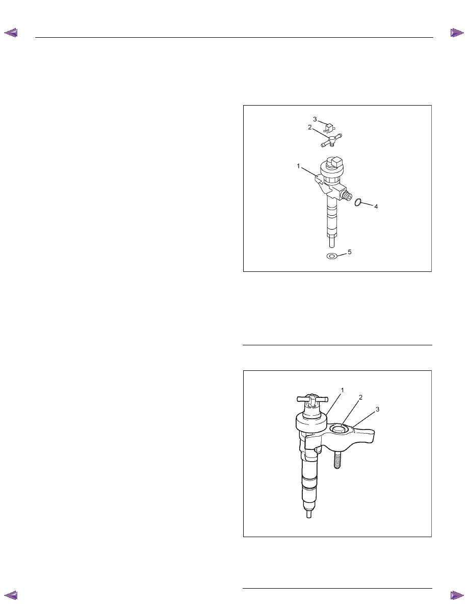
1. Install the new gasket and O-ring to each fuel 

injector. 

Note: Do not reuse the clips (3). 


RTW66CSH000101

Legend 

 1. Fuel 

Injector 

  2.  Leak Off Pipe 

 3. Clip 

 4. O-ring 

 5. Gasket 


2. Install the fuel injector clamps. Refer to the 

illustration. 


RTW56CSH000601

Legend 

 1. Fuel 

Injector 

 2. Bolt 

  3.  Fuel Injector Clamp 


6C-16  FUEL SYSTEM (4JK1/4JJ1) 

3. Apply Engine oil to the threads and seating

surfaces of the clamp bolts. 

4.  Install the fuel injector clamps to the cylinder head.

5.  Temporarily tighten the clamp bolts. 

6.  Apply a thin coat of engine oil to the outer surface

of the fuel injector side sleeve nuts. 

7.  Install the fuel injector pipes to the position shown

in the illustration. 

8.  Use a spanner to carefully tighten the sleeve nuts

until the fuel injector pipes contact the fuel injector

and fuel rail. 

9.  Tighten the fuel injector pipe clips to the specified

torque. 

Tightening torque: 8 N

⋅⋅⋅⋅m (0.8 kg⋅⋅⋅⋅m / 69 lb in) 


RTW76CMH000101

Legend 

 1. Fuel 

Injector 

 2. Pipe 

Clip 


10. Tighten the injection pipes to the specified torque.

Tightening torque: 30 N

⋅⋅⋅⋅m (3.1 kg⋅⋅⋅⋅m / 22 lb ft) 


RTW76CSH000201

Legend 

 1. Clamp 

Bolt 

 2. Sleeve 

Nut 


11. 

Tighten the fuel injector clamp bolts to the 

specified torque. 

Tightening torque: 26 N

⋅⋅⋅⋅m (2.7 kg⋅⋅⋅⋅m / 20 lb ft) 

12. Tighten the engine oil level gauge guide tube. 

Tightening torque: 25 N

⋅⋅⋅⋅m (2.5 kg⋅⋅⋅⋅m / 18 lb ft) 

13. Install the cylinder head cover. 


Refer to the install procedure for the cylinder head 

cover in this manual. 


FUEL SYSTEM (4JK1/4JJ1)  6C-17 

Record the Fuel Injector ID Code Data from 
each injector housing 

1.  Remove each fuel injector harness connector. 

2. Record all numbers of each cylinder on the

harness connector housing. The correct order for

the fuel injector ID codes of the following

illustration is as follows: 


5F 05 00 FB 00 F7 08 F5 19 FF 04 49 


RTW76ESH002601

Legend 

  1.  Fuel Injector ID Code 

 2. Fuel 

Injector 


Programming Fuel Injector ID Codes 

1.  Install a scan tool.  

2.  Turn ON the ignition, with the engine OFF. 

3. 

Select Diagnostics > appropriate vehicle

identification > 4JK1 or 4JJ1 > Programming >

Replace Injector. 

4. In order to get programming approval, the on-

screen displays a message to user. Get

programming approval from the TIS 2000 using

the following procedure: 

a. Connect a scan tool to the terminal that

installed TIS 2000 with the latest software and

the hardware key is plugged into port. 

b.  Turn ON the scan tool and keep at title screen.

c.  Launch the TIS application.  

d.  Select the Security Access at the main screen.

e.  Highlight the "Tech" 2 on the Diagnostic Tool

Selection screen and click "Next". 

f.  Click "Close" on the Security Access Enabled

screen.  


g.  Turn OFF the scan tool.  

h.  Disconnect the scan tool from the terminal. 

5.  Reinstall a scan tool to the vehicle.  

6.  Turn ON the ignition, with the engine OFF. 

7. 

Select Diagnostics > appropriate vehicle 

identification > 4JK1 or 4JJ1 > Programming > 

Replace Injector. 

8.  Enter 24 figures of replaced fuel injector ID code.

9.  After complete the programming, turn OFF the 

ignition for 30 seconds.  

10.Start the engine and let idle.  

11.Inspect for a proper engine running condition and 

for no DTC's. Refer to the Diagnostic System 

Check - Engine Controls if needed. 


6C-18  FUEL SYSTEM (4JK1/4JJ1) 

Torque Specifications 


RTW76CLF000201 


Content   ..  387  388  389  390   ..