Isuzu KB P190. Manual - part 385


  Index      Isuzu     Isuzu KB P190 - service repair manual 2007 year


Search            


Content   ..  383  384  385  386   ..


Isuzu KB P190. Manual - part 385


ENGINE COOLING (4JK1/4JJ1)  6B-17 

Fan Clutch with Cooling Fan 

Inspection and Repair 

Make necessary correction or parts replacement if
wear, damage or any other abnormal conditions are 
found through inspection. 


Visually inspect for damage, leak (silicon grease) or
other abnormal conditions. 

1. Inspection (on-vehicle) 

a) Turn the fan clutch by hand when in a low

temperature condition before starting the

engine, and confirm that it can be turned

readily. 

b) Start the engine to warm it up until the

temperature at the fan clutch portion gets to

around 85°C (185°F). Then stop the engine and

confirm that the fan clutch can be turned with

considerable effort (clutch torque) when turned

by hand. 


If the fan clutch rotates more readily, however,

this indicates that the silicone grease is leaking

internally. 


Replace the fan clutch with a new one. 


RTW56ASH025401


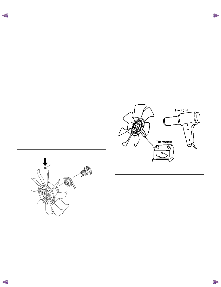
2.  Inspection (in unit) 


Warm up the bimetal of the fan clutch by using the 

heat gun until the temperature gets to about 85°C 

when measured with the thermistor.   Then confirm 

that the fan clutch can be turned with considerable 

effort (clutch torque). 


If the fan clutch rotates more readily at this time, 

this indicates that the silicone grease is leaking 

internally. 


Replace the fan clutch with a new one. 


033RY00011


6B-18  ENGINE COOLING (4JK1/4JJ1) 

Special Tools 

ILLUSTRATION 

PART NO. 

PART NAME 


5-8840-0277-0 

Cap tester 


5-8840-2603-0 

Adapter 


FUEL SYSTEM (4JK1/4JJ1)  6C-1 

SECTION 6C 

FUEL SYSTEM 

TABLE OF CONTENTS 


Fuel System .......................................................  6C-2

Service Precautions ........................................  6C-2

Trouble Shooting .............................................  6C-8

Fuel System Check ......................................... 6C-10

Fuel Filter Assembly........................................... 6C-12

Components.................................................... 6C-12

Removal .......................................................... 6C-12

Installation ....................................................... 6C-12

Fuel Filter Cartridge............................................ 6C-13

Removal .......................................................... 6C-13

Installation ....................................................... 6C-13

Fuel Injector........................................................ 6C-14

Components.................................................... 6C-14

Removal .......................................................... 6C-15

Installation ....................................................... 6C-15

Torque Specifications...................................... 6C-18

Fuel Rail Pressure Sensor ................................. 6C-19

Removal .......................................................... 6C-19

Installation ....................................................... 6C-19

Fuel Pressure Limiter ......................................... 6C-20

Removal .......................................................... 6C-20

Installation ....................................................... 6C-20

Fuel Rail Assembly............................................. 6C-21

Components.................................................... 6C-21

Removal .......................................................... 6C-22

Disassembly.................................................... 6C-24

Reassembly..................................................... 6C-24

Installation ....................................................... 6C-24

Torque Specifications...................................... 6C-26

Fuel Supply Pump .............................................. 6C-27

Components.................................................... 6C-27

Removal .......................................................... 6C-28

Installation ....................................................... 6C-33

Torque Specifications...................................... 6C-38

Fuel Sedimenter Switch ..................................... 6C-39

Inspection ........................................................ 6C-39

Fuel Tank and Fuel Cooler................................. 6C-40

Fuel Tank and Associated Parts ..................... 6C-40

Removal .......................................................... 6C-41

Installation ....................................................... 6C-41


Fuel Gauge Unit ................................................. 6C-42

Fuel Gauge Unit and Associated Parts ........... 6C-42

Removal .......................................................... 6C-43

Installation ....................................................... 6C-43

Special Tool .................................................... 6C-43

Fuel Tube/Quick-Connector Fittings .................. 6C-44

Precautions ..................................................... 6C-44

Cautions During Work..................................... 6C-44

Removal .......................................................... 6C-44

Reuse of Quick-Connector.............................. 6C-45

Assembling Advice.......................................... 6C-45

Filler Neck .......................................................... 6C-46

Removal .......................................................... 6C-46

Installation ....................................................... 6C-46

Fuel Filler Cap .................................................... 6C-47

General Description ........................................ 6C-47

Inspection........................................................ 6C-47

6C-2  FUEL SYSTEM (4JK1/4JJ1) 

Fuel System 

Service Precautions 

Parts of the fuel system such as the internal part of the
fuel injector, and holes and clearances that form
passages for fuel are finished to a very high degree of
accuracy. They are therefore highly sensitive to foreign
matter and the entry of foreign matter could cause
damage to the fuel passage. Therefore, effective
measures should be taken to prevent the entry of
foreign matter. 

If a water removal agent is used in the fuel then it will 
absorb moisture in the light oil and may cause rust.
Therefore, do not use a water removal agent in the fuel
tank. 

When servicing the fuel system, every precaution must
be taken to prevent the entry of foreign material into the
system. 

•  Before beginning the service procedure, wash the

fuel line and the surrounding area. 

•  Perform the service procedures with clean hands.

Do not wear work gloves. 

•  Immediately after removing the fuel hose and/or

fuel pipe, carefully tape vinyl bags over the

exposed ends of the hose or pipe. 

•  If parts are to be replaced (fuel hose, fuel pipe,

etc.) do not open the new part packaging until

installation. 

Discard gaskets and O-rings and replace them with new
ones. 


Work procedure 

•  The fuel opening must be quickly sealed when

removing the fuel pipe, injection pipe, fuel injector, 

fuel supply pump, and fuel rail. 

•  The eyebolts and gasket must be stored in a clean 

parts box with a lid to prevent adhesion of foreign 

matter. 

•  Fuel leakage could cause fires. Therefore, after 

finishing the work, wipe off the fuel that has leaked 

out and make sure there is no fuel leakage after 

starting the engine. 


Content   ..  383  384  385  386   ..