Isuzu KB P190. Manual - part 377


  Index      Isuzu     Isuzu KB P190 - service repair manual 2007 year


Search            


Content   ..  375  376  377  378   ..


Isuzu KB P190. Manual - part 377


6A-148  ENGINE MECHANICAL (4JK1/4JJ1) 
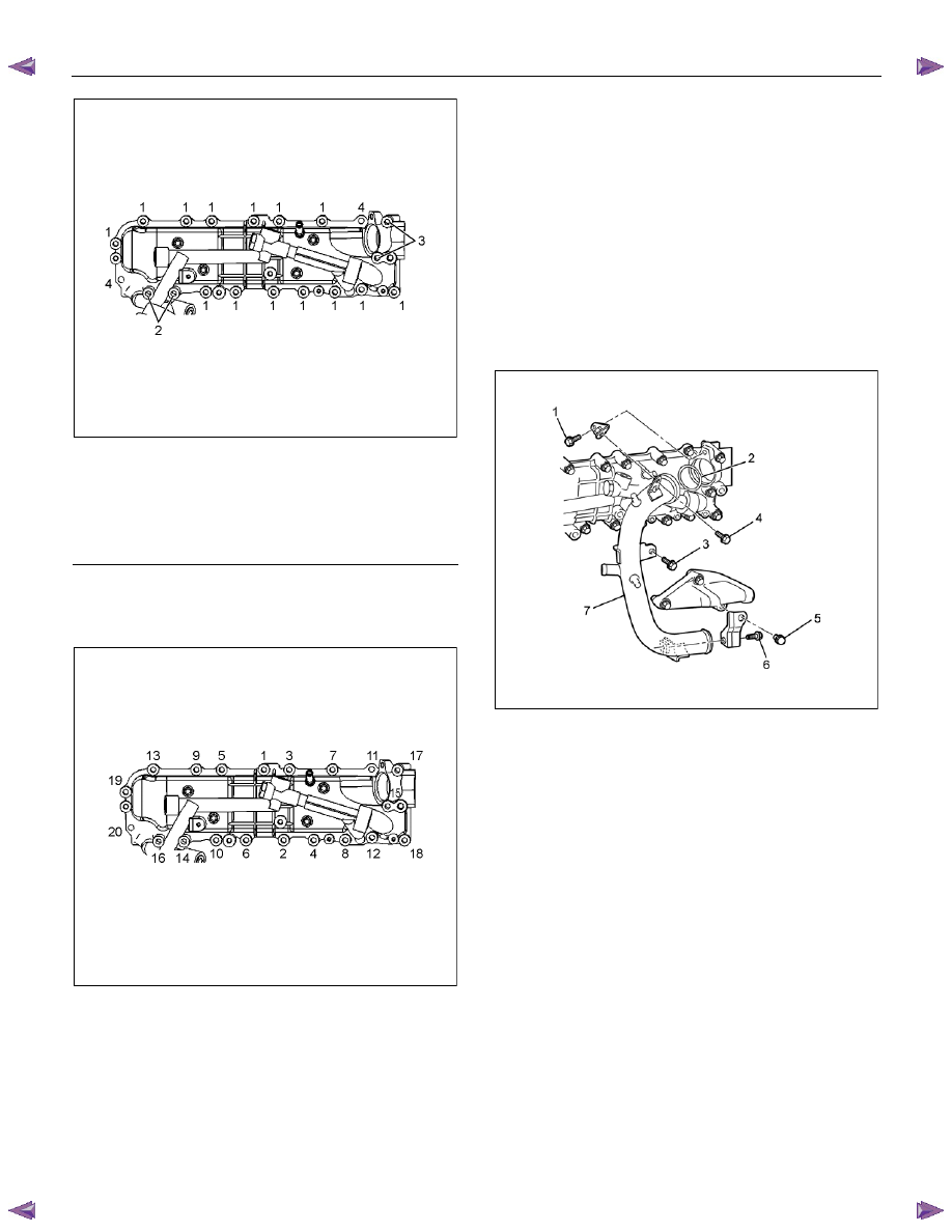


RTW56ASH013201

Legend 

  1.  Bolt 45 mm (1.77 in) 

  2.  Bolt 110 mm (4.33 in) 

  3.  Bolt 70 mm (2.76 in) 

 4. Nut 


•  Tighten the bolts to the specified torque in the

order shown in the illustration. 

Tightening torque: 25 N

⋅⋅⋅⋅m (2.5 kg⋅⋅⋅⋅m / 18 lb ft) 


RTW56ASH013301


2.  Install the water intake pipe. 

a.  Temporarily tighten the bolt (6). 

b.  Install the O-ring (2) to the water intake pipe 

(7). 

c.  Apply soapy water to the O-ring (2) and install 

the water intake pipe (7). 

•  Take care not to twist the O-ring. 

d.  Temporarily tighten the bolts. 


Temporary tightening order: 1→3→4→5 

e.  Tighten the bolts to the specified torque. 


Fully tightening order: 3→4→1→5→6 

Tightening torque: 25 N

⋅⋅⋅⋅m (2.5 kg⋅⋅⋅⋅m / 18 lb ft) 


RTW76ASH001701

3.  Install the water bypass pipe (1). 

•  After applying soapy water to O-ring, set it on 

bypass pipe and insert into the cylinder head. 


Tighten the bolts to the specified torque. 

Tightening torque: 25 N

⋅⋅⋅⋅m (2.5 kg⋅⋅⋅⋅m / 18 lb ft) 


ENGINE MECHANICAL (4JK1/4JJ1)  6A-149 


RTW56ASH008401

4.  Install the bracket of generator. 


Tighten the bolts to the specified torque. 

Tightening torque: 51 N

⋅⋅⋅⋅m (5.2 kg⋅⋅⋅⋅m / 38 lb ft) 

5.  Install the adjustment bracket of generator. 


Tighten the bolts to the specified torque. 

Tightening torque: 25 N

⋅⋅⋅⋅m (2.5 kg⋅⋅⋅⋅m / 18 lb ft) 

6.  Install the generator. 


Refer to Installation procedure for generator in this

manual. 

7.  Install the exhaust manifold. 

  Refer to Installation procedure for turbocharger 

and exhaust manifold in this manual. 


6A-150  ENGINE MECHANICAL (4JK1/4JJ1) 

Crank Case and Oil Pan 

Components 


RTW76ALF000801 

Legend 

 1. Gasket 

 2. Oil 

Strainer 

 3. Bolt 

 4. Crank 

Case 


5. 

Rear 

Plate 

 6. Bolt 

 7. Oil 

Pan 

 8. Bolt 


ENGINE MECHANICAL (4JK1/4JJ1)  6A-151 

Removal 

1.  Remove the engine assembly. 


Refer to “Engine Assembly”. 

2.  Remove the oil level gage guide tube. 


RTW56ASH015601

3.  Remove the oil pan. 


RTW56ASH015001


4. Disconnect the earth terminal (1) of crank case 

side. 


RTW76ASH001801

5.  Remove the flywheel. 


Refer to “Flywheel”. 

6.  Remove the rear plate. 


RTW76ASH001901

Legend 

 1. Rear 

Plate 

 2. Bolt 


Content   ..  375  376  377  378   ..