Isuzu KB P190. Manual - part 368


  Index      Isuzu     Isuzu KB P190 - service repair manual 2007 year


Search            


Content   ..  366  367  368  369   ..


Isuzu KB P190. Manual - part 368


6A-112  ENGINE MECHANICAL (4JK1/4JJ1) 
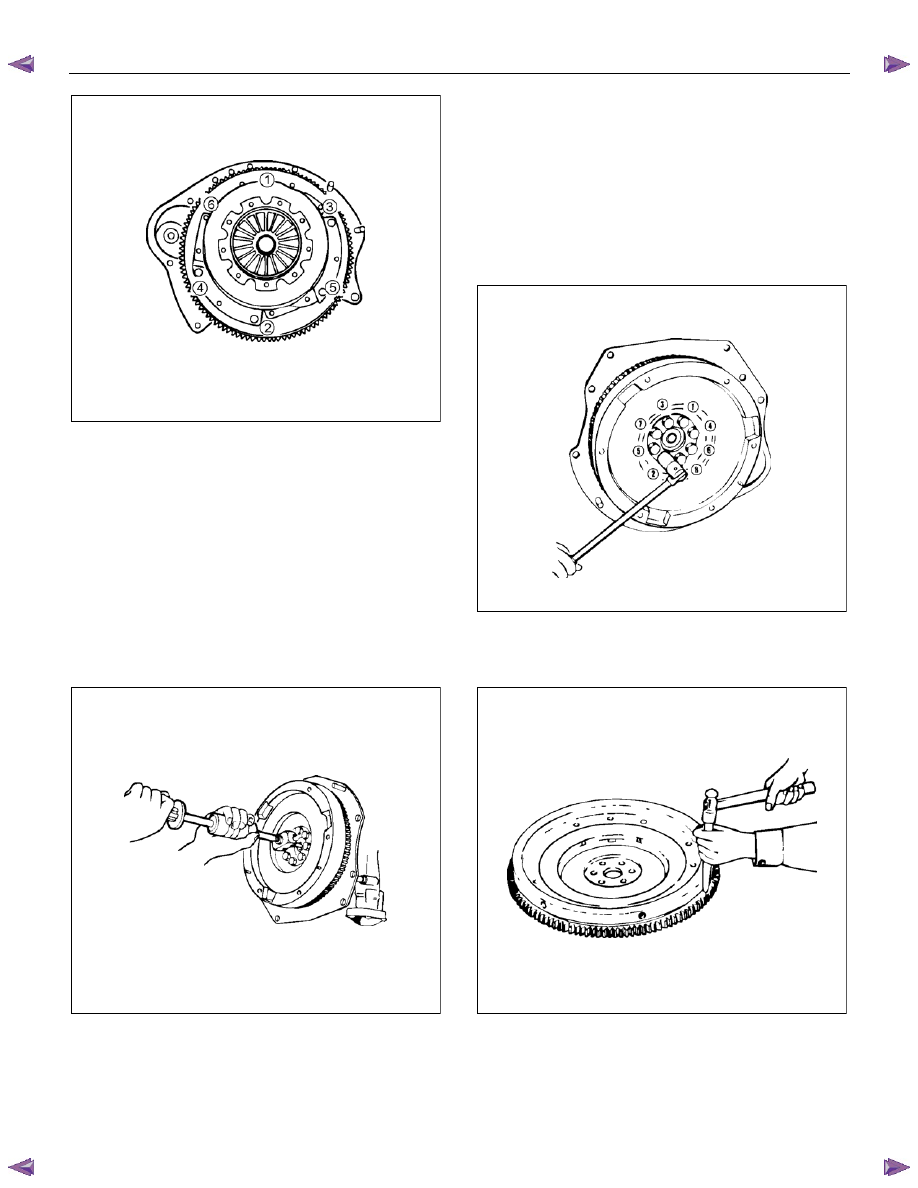


RTW56ASH014201

3.  Remove the driven plate. 

•  Remove the driven plate from the flywheel

along with the clutch aligner. 

•  Install the crankshaft stopper in the starter

installation part of the rear plate. 

Note: 
Make sure that the stopper is applied with the ring gear
and installed properly. 

 Special 

tool 


Crankshaft stopper: 5-8840-0214-0 

4.  Remove the pilot bearing. 

•  Remove the pilot bearing from the flywheel. 


015RY00018

 Special 

tool 


Pilot Bearing Remover: 5-8840-2000-0 


Sliding Hammer: 5-8840-0019-0 


5.  Remove the flywheel. 

•  Gradually loosen the flywheel installation bolts 

in the order shown in the drawing so that the 

flywheel does not rotate. 

•  After loosening the bolts, remove the stopper 

and remove the flywheel. 

•  In the case of A/T car, after loosening the 

flywheel installation bolts, remove the washer, 

flexible plate, flywheel and sleeve in this order. 


015RY00001

6.  Remove the ring gear. 

•  Put a bar on the ring gear and hit it with a 

hammer to remove it. 


LNW21BSH012001


ENGINE MECHANICAL (4JK1/4JJ1)  6A-113 

Inspection 

1. Visual inspection 

•  Inspect the flywheel friction surface for cracks

and damages, and replace it if it has

abnormality. 

•  Inspect the tooth part of the ring gear, replace

the ring gear if it has damage or serious wear.

2.  Measurement of the friction surface 

•  Measure the depth of the friction surface of the

flywheel. 

•  Adjust it if the measured value is within the

standard value and the limit. 

• If the measured value exceeds the limit,

replace the flywheel. 

  Depth of the friction surface of the flywheel 

mm (in)

Standard 18 

(0.7087) 

Limit 19 

(0.7480) 


Depth = From the pressure installation surface

to the friction surface. 


LNW21BSH011901

3.  Flywheel installation bolts. 

•  There is no damage in appearance. 
• Exchange for a new part if damage is 

extensive. 


Installation 

1.  Install the ring gear. 

•  Heat the ring gear evenly with a gas burner to 

invite thermal expansion. Do not allow the 

temperature of the gas burner to exceed 200°C 

(392°F). 

•  Install the ring gear when it is sufficiently 

heated. The ring gear must be installed with the 

chamfer facing the clutch.  

Note: 

•  Install the ring gear so that the side with a 

pattern faces forward. 

•  Shrink fit the ring gear to the flywheel. 
 

Make sure that flywheel and ring gear adhesion 

is complete. 


LNW21BSH01201

2.  Install the pilot bearing. 

•  Place the crankshaft pilot bearing right angle 

across the crankshaft bearing installation hole.

•  Tap around the edges of the crankshaft pilot 

bearing outer races with a brass hammer to 

drive the bearing into the crankshaft bearing 

installation hole. 

 Special 

tool 


Pilot Bearing Installer: 5-8522-0024-0  


6A-114  ENGINE MECHANICAL (4JK1/4JJ1) 


015RY00010

3.  Install the flywheel. 

•  Install the flywheel of the crankshaft, tighten

them in the order shown in the illustration. 

•  Apply molybdenum disulfide on the screw part

and setting face of the bolt. 

•  Install the crankshaft stopper on the starter

installation part of the rear plate. 

Tightening torque: 

1st step = 59 N

⋅⋅⋅⋅m (6.0 kg⋅⋅⋅⋅m / 43 lb ft) 

2nd step = 60° - 90° (degrees) 

 Special 

tool 


Crankshaft stopper: 5-8840-0214-0 


015RY00001

4.  Install the driven plate. 

•  Use a clutch aligner to install the driven plate

on the flywheel. 


LNW21BSH002601

Legend 

 1. Clutch 

Aligner 


5.  Install the clutch pressure plate. 

•  Install the pressure plate on the flywheel so that 

the installation hole of the pressure plate 

matches with the dowel pins of the flywheel. 

•  Tighten the pressure plate in the order shown 

in the illustration. 

Tightening torque: 18 N

⋅⋅⋅⋅m (1.8 kg⋅⋅⋅⋅m / 13 lb ft) 


RTW56ASH023301

6.  Install the transmission assembly. 


Refer to removal procedure for “TRANSMISSION”.


ENGINE MECHANICAL (4JK1/4JJ1)  6A-115 

Torque Specifications 


Special Tools 

ILLUSTRATION 

PART NO. 

PART NAME 


ILLUSTRATION 

PART NO. 

PART NAME 


5-8840-0214-0 

Crankshaft stopper 


5-8522-0024-0 

Pilot Bearing Installer 


5-8840-2000-0 

Pilot Bearing Remover 


5-8840-0019-0 

Sliding Hammer 


Content   ..  366  367  368  369   ..