Isuzu KB P190. Manual - part 356


  Index      Isuzu     Isuzu KB P190 - service repair manual 2007 year


Search            


Content   ..  354  355  356  357   ..


Isuzu KB P190. Manual - part 356


6A-64  ENGINE MECHANICAL (4JK1/4JJ1) 

3.  Install the sub gear assembly. 

•  Clamp the camshaft in a vise. Insert soft metal

protectors (aluminum) between the vise

surfaces and the camshaft. Press against the

pin on the left side of the camshaft gear spring

(3) to make a gap on the right side of the

spring. Push the spring into place. 

•  Align the sub gear pin (2) with the hole in the 

right side of the camshaft gear damper spring 

(3). Press the sub-gear into place. 


RTW56ASH006701

Legend 

 1. Snap 

Ring 

 2. Sub-gear 

 3. Damper 

Spring 

 4. Camshaft 

Gear 


•  Use a pair of snap ring pliers to snuggly install

the snap ring. 


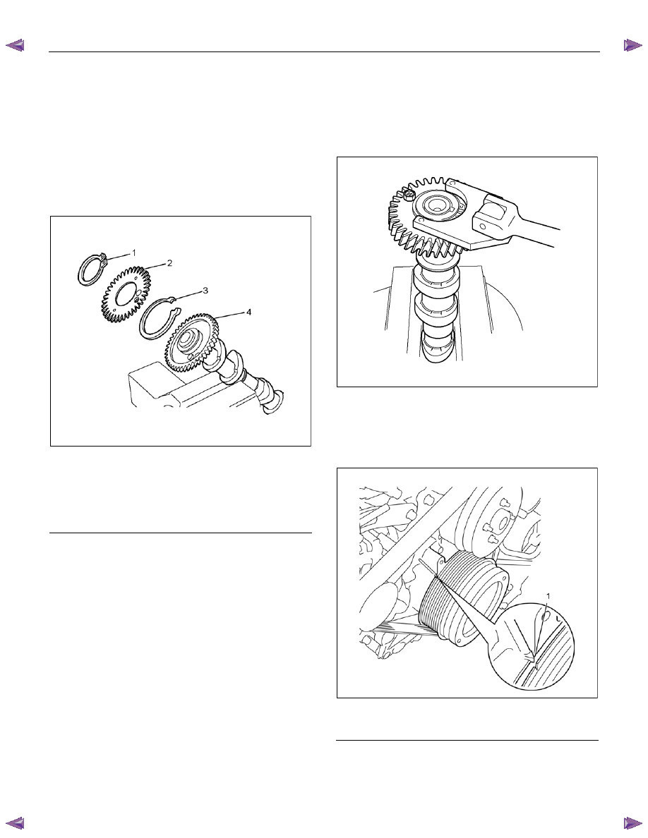
4.  Tighten sub gear setting bolt. 

•  Use 5-8840-2591-0 to turn sub gear to right

direction until it aligns with the M5 bolt hole 

between camshaft driven gear and sub gear. 

•  Tighten the M5 bolt to a suitable torque to 

prevent the sub-gear from moving. 


RTW56ASH006801


Installation 

1.  Check the crankshaft to make the No. 1 cylinder 

meet the compression TDC. 


RTW76ASH001301

Legend 

 1. TDC 


ENGINE MECHANICAL (4JK1/4JJ1)  6A-65 

2.  Install the camshaft assembly. 

•  Align timing mark on intake camshaft and

exhaust camshaft to idle gear D. 


RTW56ASH007001

Legend 

  1.  Exhaust Camshaft Gear 

  2.  Intake Camshaft Gear 

  3.  Idle Gear D 


3.  Camshaft bearing caps, tighten ten bolts on one

side bank to the specified torque. 
• Apply engine oil to camshaft journal and

bearing surface of camshaft bearing caps. 


RTW56ASH018401


4.  Check that the alignment marks (camshaft bearing 

cap and camshaft) are aligned. 


RTW56ASH006901

Legend 

 1. Align mark on intake camshaft and exhaust 

camshaft to mark of bearing cap 


•  Apply engine oil over the screw part and tighten 

up the bearing cap with the prescribed torque.

Tightening torque: 18 N

⋅⋅⋅⋅m (1.8kg⋅⋅⋅⋅m / 13 lb ft) 

5.  Remove the M5 lock bolt of fixing sub gear. 

6.  Adjustment of valve clearance. 

•  Refer to installation procedure for inspection / 

adjustment of valve clearance in this manual. 

7. Install the baffle plate. Tighten the bolts to the 

specified torque. 

Tightening torque: 10 N

⋅⋅⋅⋅m (1.0 kg⋅⋅⋅⋅m/87 lb in) 

8.  Install the cylinder head cover. 


Refer to "Cylinder Head Cover". 

9.  Install the engine cover. 


6A-66  ENGINE MECHANICAL (4JK1/4JJ1) 

Torque Specifications 


RTW56AMF001701 


Special Tools 

ILLUSTRATION 

PART NO. 

PART NAME 


5-8840-2591-0 

Camshaft gear tool 


ENGINE MECHANICAL (4JK1/4JJ1)  6A-67 

Valve Stem Seal and Valve Spring 

Components 


RTW56ALF001301 

Legend 

  1.  Exhaust Rocker Arm Shaft Assembly 

 2. Bolt 

(Long) 

 3. Bolt 

(Short) 

  4.  Intake Rocker Arm Shaft Assembly 

  5.  Fuel Injector Assembly 

 6. Bolt 

  7.  Fuel Injector Clamp 


8. 

Pin 

  9.  Spring Lower Seat 

  10.  Valve Stem Oil Seal 

 11.  Valve Spring 

  12.  Spring Upper Seat 

 13.  Split Collar 

  14.  Valve Stem End Cap 


Content   ..  354  355  356  357   ..