Isuzu KB P190. Manual - part 243


  Index      Isuzu     Isuzu KB P190 - service repair manual 2007 year


Search            


Content   ..  241  242  243  244   ..


Isuzu KB P190. Manual - part 243


6C – 8   FUEL SYSTEM 

FUEL TANK 

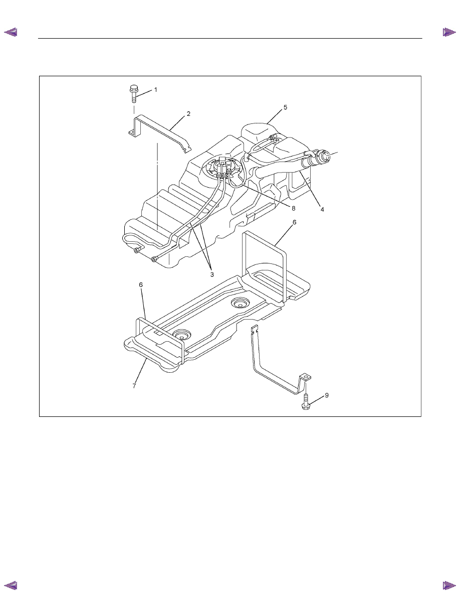
Fuel Tank and Associated Parts 


RTW46CLF000801 


Legend 


1. Bolt; Fuel Tank 


2. Fuel Tank Band 


3. Fuel Tube/Quick Connector 


4. Fuel Filler Hose 


5. Fuel Tank 


6. Under Shield Band (only specified 

model) 


7. Under Shield (only specified model) 


8. Evapo Pipe (only specified model) 


9. Bolt; Fuel Tank 


FUEL SYSTEM    6C – 9 


Removal 

CAUTION:  When repair to the fuel system has been 
completed, start engine and check the fuel system for 
loose connection or leakage. For the fuel system 
diagnosis, see Section “Driveability and Emission". 
1.  Disconnect battery ground cable. 

2.  Loosen slowly the fuel filler cap. 

NOTE: Be careful not to spouting out fuel because of change 
the pressure in the fuel tank. 

NOTE: Cover opening of the filler neck to prevent any dust
entering. 

3.  Jack up the vehicle. 

4.  Support underneath of the fuel tank with a lifter. 

5.  Remove the inner liner of the wheel house at rear left side.

6.  Remove fixing bolt of the filler neck from the body. 

7.  Disconnect the quick connector (3) of the fuel tube from the 

fuel pipe. 

NOTE: Cover the quick connector to prevent any dust entering 
and fuel leakage. 

NOTE: Refer to “Fuel Tube/Quick Connector Fittings” in this
section when performing any repairs. 

8.  Remove fixing bolt (1) of the tank band and remove the 

tank band (2). 

9.  Disconnect the pump and sender connector on the fuel 

pump and remove the harness from weld clip on the fuel

tank. 

10. Lower the fuel tank (5). 

NOTE: When lower the fuel tank from the vehicle, don’t scratch 
each hose and tube by around other parts. 


Installation 

1.  Raise the fuel tank. 

NOTE: When raise the fuel tank to the vehicle, don’t scratch 
each hose and tube by around other parts. 

2.  Connect the pump and sender connector to the fuel pump

and install the harness to weld clip on the tank. 

NOTE: The connector must be certainly connected against 
stopper. 

3.  Install the tank band and fasten bolt. 

Torque 

N·m (kg·m / lb ft)

68 (6.9 / 50) 

NOTE: The anchor of the tank band must be certainly installed
to guide hole on frame. 

4.  Connect the quick connector of the fuel tube to the fuel pipe 

and the evapo tube from evapo joint connector. 

NOTE: Pull off the left checker on the fuel pipe. 

NOTE: Refer to “Fuel Tube/Quick Connector Fittings” in this
section when performing any repairs. 

6C – 10   FUEL SYSTEM 

5.  Install the filler neck to the body with bolt. 

6.  Install the inner liner of the wheel house at rear left side. 

7.  Remove lifter from the fuel tank. 

8.  Lower the vehicle. 

9.  Tigten the filler cap until at least three clicks. 

10. Connect the battery ground cable. 


FUEL SYSTEM    6C – 11 

FUEL GAUGE UNIT 

Fuel Gauge Unit and Associated Parts 


RTW46CLF000901 


Legend 


1. Fuel Feed Port 


2. Fuel Return Port 


3. Fuel Emission Port 


4. Fuel Gauge Unit and Sender Assembly


5. Connector; Fuel Gauge Unit 


6. Fuel Tube/Quick Connector 


7. Retainer Ring (Fuel Gauge Unit Lock) 


8. Seal; Fuel Gauge Unit 


9. Fuel Tank Assembly 

  10. Evapo Tube/Quick Connector 


Content   ..  241  242  243  244   ..