Isuzu KB P190. Manual - part 218


  Index      Isuzu     Isuzu KB P190 - service repair manual 2007 year


Search            


Content   ..  216  217  218  219   ..


Isuzu KB P190. Manual - part 218


ENGINE MECHANICAL   6A – 67 


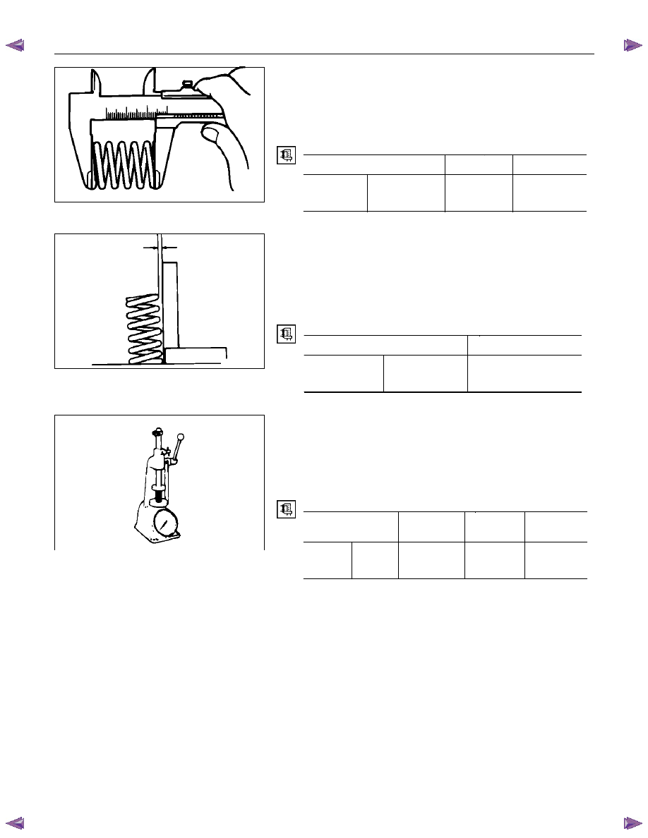
Valve Spring Free Height 

Use a vernier caliper to measure the valve spring free height. 
If the measured value is less than the specified limit, the valve 
spring must be replaced. 


Spring Free Height 

mm (in)

 Standard 

Limit 

4JA1T (L) 

4JA1TC, 

4JH1TC 

Single spring

48.0 (1.89) 

47.1 (1.85) 


Valve Spring Squareness 

Use a surface plate and a square to measure the valve spring 
squareness. 
If the measured value exceeds the specified limit, the valve 
spring must be replaced. 


Spring Squareness 

mm (in)

 Limit 

4JA1T (L) 

4JA1TC, 

4JH1TC 

Single spring 

1.7 (0.070) 


Valve Spring Tension 

Use a spring tester to measure the valve spring tension. 

If the measured value is less than the specified limit, the valve 
spring must be replaced. 


Valve Spring Tension 

N (kg/lb)


Compressed 

Height 

Standard Limit 

4JA1T (L)

4JA1TC,

4JH1TC

Single 
spring

38.9mm 

(1.53in) 

296.0 

(30.2/66.4) 

257.7 

(26.3/57.9)


011LX024

014RY00025

011LX026

6A – 68  ENGINE MECHANICAL 


ROCKER ARM SHAFT AND ROCKER ARM 

Rocker Arm Shaft Run-Out 
1.  Place the rocker arm shaft on a V-block. 

2.  Use a dial indicator to measure the rocker arm shaft 

central portion run-out. 

If the run-out is very slight, correct the rocker arm shaft 
run-out with a bench press. The rocker arm must be at cold 
condition. 

If the measured rocker arm shaft run-out exceeds the 
specified limit, the rocker arm shaft must be replaced. 


Rocker Arm Shaft Run-Out 

mm (in)

Limit 

0.3 (0.012) 


Rocker Arm Shaft Outside Diameter 

Use a micrometer to measure the rocker arm fitting portion 
outside diameter.


If the measured value is less than the specified limit, the rocker 
arm shaft must be replaced.


Rocker Arm Shaft Outside Diameter 

mm (in)

Standard Limit 

18.98–19.00 (0.747–0.748)

18.90 (0.744) 


Rocker Arm Shaft and Rocker Arm Clearance 

1.  Use either a vernier caliper or a dial indicator to measure 

the rocker arm inside diameter. 


Rocker Arm Inside Diameter 

mm (in)

Standard Limit 

19.010–19.030 

 (0.748–0.749) 

19.100 (0.752) 


2.  Measure the rocker arm shaft outside diameter. 

If the measured value exceeds the specified limit, replace 
either the rocker arm or the rocker arm shaft. 


Rocker Arm Shaft and Rocker Arm Clearance 

mm (in)

Standard Limit 

0.01–0.05 

 (0.0004–0.0020) 

0.20 (0.008) 

015LX009

014RY00024

015LX008

ENGINE MECHANICAL   6A – 69 


3.  Check that the rocker arm oil port is free of obstructions. 

If necessary, use compressed air to clean the rocker arm 
oil port. 


Rocker Arm Correction 

Inspect the rocker arm valve stem contact surfaces for step 
wear (1) and scoring (2).


If the contact surfaces have light step wear or scoring, they 
may be honed with an oil stone.


If the step wear or scoring is severe, the rocker arm must be 
replaced.


CYLINDER BODY 

Cylinder Body Upper Face Warpage 

1.  Remove the cylinder body dowel. 

2.  Remove the cylinder liner. 

Refer to "Cylinder Liner Replacement". 


3.  Use a straight edge (1) and a feeler gauge (2) to measure 

the four sides and the two diagonals of the cylinder body 
upper face. 

If the measured values exceeds the limit, the cylinder body 
must be replaced. 


Cylinder Body Upper Face Warpage 

mm (in)

Standard Limit 

0.05 (0.002) or less 

0.20 (0.008) 


Cylinder Body Height  (H) (Reference)  

mm (in)

Standard 

4JA1T(L), 4JA1TC : 244.945-245.055 (9.6435-9.6478) 

4JH1TC : 269.945-270.055 (10.6277-10.6320) 

4.  Reinstall the cylinder liner. 

Refer to "Cylinder Liner Replacement". 

5.  Reinstall the cylinder body dowel. 


014RY00024

012R100001

012RY00009

014RY00023

6A – 70  ENGINE MECHANICAL 


Cylinder Liner Bore Measurement 

Use a cylinder indicator to measure the cylinder bore at 
measuring point (1) in the thrust (2-2) and axial (3-3) directions 
of the crankshaft. 

Measuring Point (1): 20 mm (0.79 in) 

If the measured value exceeds the specified limit, the cylinder 
liner must be replaced. 


Cylinder Liner Bore 

mm (in)

 Standard 

Limit 

4JA1T(L), 4JA1TC

93.00 (3.6614) 

93.08 (3.6646) 

4JH1TC 

95.40 (3.7559) 

95.48 (3.7590) 

NOTE: 

The inside of the dry type cylinder liner is chrome 
plated. It cannot be rebored or honed. 

If the inside of the cylinder liner is scored or 
scorched, the cylinder liner must be replaced. 


Cylinder Liner Projection Inspection 

1.  Hold a straight edge along the top edge of the cylinder liner 

to be measured. 

2.  Use a feeler gauge to measure each cylinder liner 

projection. 


Cylinder Liner Projection 

mm (in)

Standard 

0-0.1 (0-0.004) 

The difference in the cylinder liner projection height 
between any two adjacent cylinders must not exceed 0.03 
mm (0.0012 in). 


Cylinder Liner Replacement 

Cylinder Liner Removal 

1.  Insert the cylinder liner remover (1) into the cylinder body 

(from the lower side of the cylinder body) until it makes firm 
contact with the cylinder liner. 

Cylinder Liner Remover  : 5-8840-2039-0 (4JA1L/TC) 


: 5-8840-2304-0 (4JH1TC) 

2.  Use a bench press (2) to slowly force the cylinder liner 

from the cylinder body. 


NOTE: 

Take care not to damage the cylinder body upper face 
during the cylinder liner removal procedure. 

3.  Measure the cylinder body upper face warpage. 

Refer to "Cylinder Body Upper Face Warpage". 

012RY00010

012LX016

012RY00012


Content   ..  216  217  218  219   ..