Isuzu KB P190. Manual - part 1497


  Index      Isuzu     Isuzu KB P190 - service repair manual 2007 year


Search            


Content   ..  1495  1496  1497  1498   ..


Isuzu KB P190. Manual - part 1497


11B-34 ANTITHEFT SYSTEM 

Program Vehicle Options 

1.  Select “Body” and “Antitheft”. 

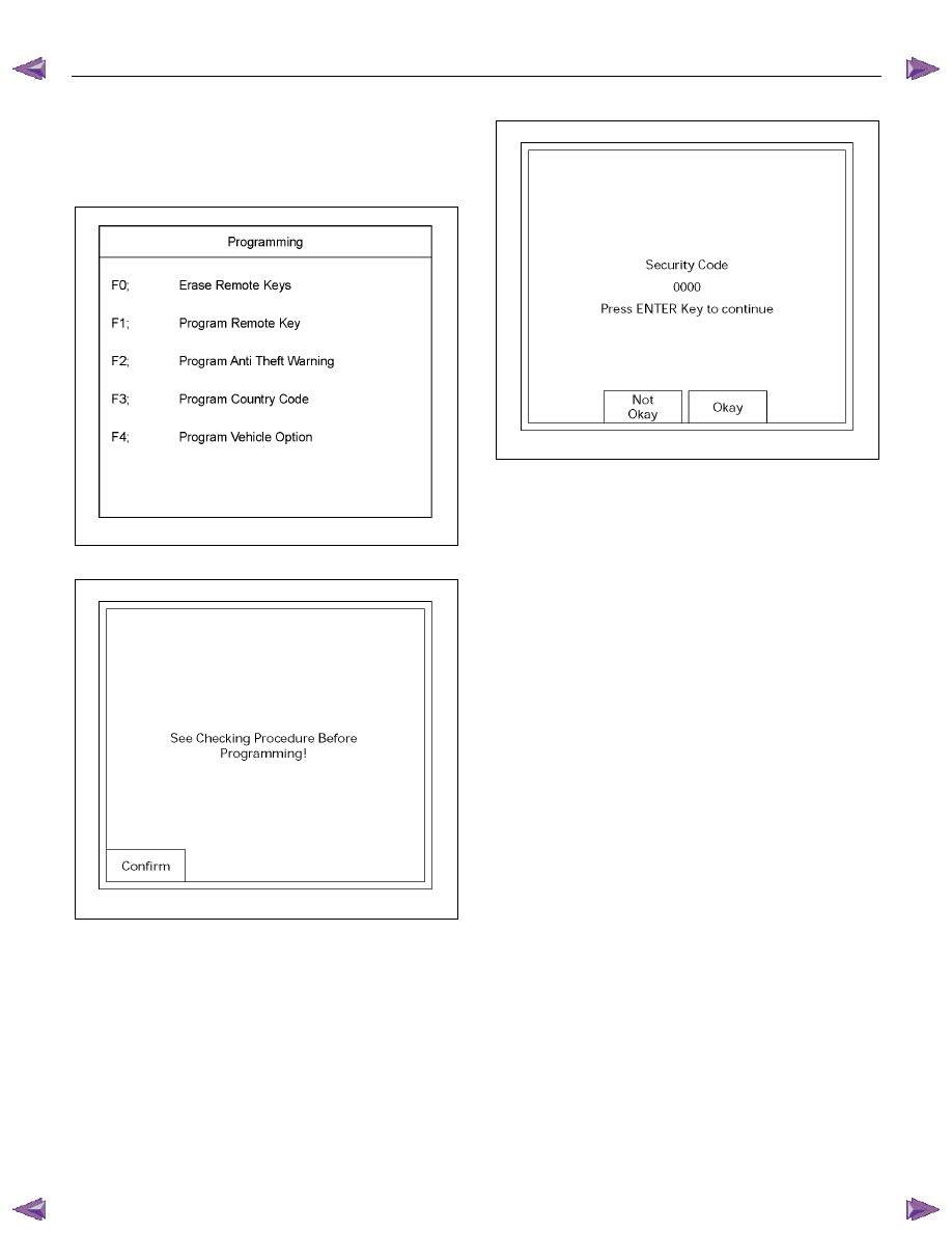
2. Select “Programming”. 

3.  Select “Program Vehicle Options“. 


RAW4B0SH000601


The following screen shows up. 


060R200289


4.  Confirm the following screen shows up. 


060R200284

5.  Input the vehicle options. 


ANTITHEFT SYSTEM 11B-35 

Tech-2 Data List 

No. Data 

List 

Units 

1 Battery 

Voltage 

2 ‘KEY-IN’ 

Status 

ON/OFF 

CDLS-Motor Voltage (Central Door Locking System) 

Accident Sensor (Crash Sensor) 

Active/Inactive 

5 Remote 

Key 

Active/Inactive 

Remote-Key Detected 

Remote Key No. 

Key Function Detected 

Lock/Unlock 

Prev. Detected Remote-Key (Previously) 

Remote Key No. 

Previously Key Function 

Lock/Unlock 

10 

Remote-Key 1 Status 

In Range/Not Programmed 

11 

Remote-Key 2 Status 

In Range/Not Programmed 

12 

Remote-Key 3 Status 

In Range/Not Programmed 

13 

Remote-Key 4 Status 

In Range/Not Programmed 

14 

Remote-Key 5 Status 

In Range/Not Programmed 

15 

Front Door Unlock Switch 

Active/Inactive 

16 

Front Door Lock Switch 

Active/Inactive 

17 

Front Door Lock Status 

Active/Inactive 

18 

Auto Door Unlock Switch 

Active/Inactive 

19 

Auto Door Lock Switch 

Active/Inactive 

20 

Auto Door Lock Status 

Active/Inactive 

21 

Trunk Signal Switch 

*Not used 

Open/Closed

22 Doorknob 

Switch 

Open/Closed 


23 Doorknob 

Status 

Lock/Unlock 


24 

Trunk Doorknob Switch 

*Not used 

Open/Closed

25 

Trunk Doorknob Status 

*Not used 

Lock/Unlock 

26 

Driver Door Switch 

Open/Closed   

27 

Driver Door Status 

Open/Closed   

28 

All Door Switch 

Open/Closed   

29 

All Door Status 

Open/Closed   

30 

Door lock Tamper Switches 

Open/Closed   

31 

Engine Hood Switch 

Open/Closed   

32 

Engine Hood Status 

Open/Closed   

33 

Trunk Switch 

*Not used 

Open/Closed

34 

Trunk Status 

*Not used 

Open/Closed

35 

Pane Breakage Connected 

*Not used 

Yes/No 

36 

Pane Breakage Status 

*Not used   Disabled/Abled 

37 

CDLS-Motor Current (Central Door Locking System) 

38 

CDLS-Motor Unlock (Central Door Locking System) 

39 

CDLS-Motor Lock (Central Door Locking System) 

40 Overflow 

Protection 

Active/Inactive 

41 Turn 

Signal 

Active/Inactive 

42 Horn 

Connected 

Yes/No 

43 Horn 

Signal 

Active/Inactive 

44 Theft 

LED 

ON/OFF 

45 

CDLS-Status (Central Door Locking System) 

Lock/Unlock 

46 Selftest 

Request 

Active/Inactive 

47 Last 

Use 

— 

48 Theft 

Status 

Disabled/Abled 

49 Alarm 

Status 

Active/Inactive 

50 

Security Wait Time 

Active/Inactive 

11B-36 ANTITHEFT SYSTEM 


Diagnosis 

Diagnostic procedure 

•  Once the cause of DTC is repaired or gone,

engine can be operated normally, and present

DTC becomes history code. 

•  History code is canceled by no repeat failure on 25 

consequence ignition key on afterward. 

•  History code cannot be canceled by battery

connector disconnected. 

Clearing Diagnostic Trouble Codes 

IMPORTANT: Do not clear DTCs unless directed to do 
so by the service information provided for each 
diagnostic procedure. When DTCs are cleared, the 
Failure Record data which may help diagnose an 
intermittent fault will also be erased from memory. 

Verifying Vehicle Repair 

Verification of vehicle repair will be more 
comprehensive for vehicles with immobilizer system 
diagnostic. Following a repair, the technician should 
perform the following steps: 

1.  Review and record the Fail Records for the DTC

which has been diagnosed. 

2.  Clear DTC (s). 

3.  Operate the vehicle within conditions noted in the

Fail Records. 

4.  Monitor the DTC status information for the DTC

which has been diagnosed until the diagnostic test

associated with that DTC runs. 

Following these steps are very important in verifying 
repairs on immobilizer systems. Failure to follow these 
steps could result in unnecessary repairs. 

Diagnostic Aids 

An intermittent may be caused by the following: 

•  Poor connections. 
•  Miss routed harness. 
•  Rubbed through wire insulation. 
•  Broken wire inside the insulation. 

Check for the following conditions: 

•  Poor connection at ACU-Inspect harness

connectors for backed out terminals, improper

mating, broken locks, improperly formed or

damaged terminals, and poor terminal to wire

connection. 

•  Damaged harness-Inspect the wiring harness for

damage. 


If the harness appears to be OK, observe the data 

display on the Tech2 while moving connectors and 

wiring harnesses related to the switch or actuator.


A change in the display will indicate the location of 

the fault. 

  If DTC cannot be duplicated, the information 

included in the Failure Records data can be useful 

in determined vehicle mileage since the DTC was 

last set. 

  If it is determined that the DTC occurs 

intermittently, performing the DTC Diagnostic 

Chart may isolate the cause of the fault. 

NOTE: Breakage of antitheft fuse does not operate 
antitheft system. Check LED lamp flashes at this time.


Check the Electro-Magnetic Interference (EMI) 

•  Location of vehicle check 
 

Move the vehicle to a new location and perform 

the check again. 

•  Non-OEM Parts. 
 

Switch is “OFF” or remove the Non-OEM parts and 

perform the check again. 

•  Other 
 

Remove the accessory and another key from key.


Check the other items. 

•  Battery voltage is low. 
•  Antitheft programming functions. 
 

Must be programmed antitheft system. 

•  Registration for security code, antitheft control unit 

parts number. 

•  Key switch operation. 
 

Antitheft system may detect a history DTC by the 

timing of ON-OFF of a key switch. 

•  Active the antitheft system. 
•  Keyless entry system is malfunction. 
•  Immobilizer system is malfunction. 


Check the operation 

Check the operation "Lock / unlock" by using transmitter 
(key) on the vehicle. 


ANTITHEFT SYSTEM 11B-37 

Diagnostic Trouble Code (DTC) List For Antitheft 

DTC Description 

13 

Security code not yet programmed 

14 

No remote key programmed 

16 

Door lock actuators short circuit to ground 

20 

Broken wire to door lock actuators 

21 

Remote key 1 with random code out of capture range 

22 

Remote key 2 with random code out of capture range 

23 

Remote key 3 with random code out of capture range 

24 

Remote key 4 with random code out of capture range 

25 

Remote key 5 with random code out of capture range 

28 

Input immobilizer short circuit to ground 

29 

Broken wire to immobilizer 

31 

Actuator driver door defect 

32 

Actuator passenger door defect 

36 

Broken wire to driver door 

37 

Broken wire to passenger door 

41 

Driver door switch unlock defect 

42 

Driver door switch lock defect 

43 

Driver door switch dead lock defect 

44 

Passenger door switch lock defect 

45 

Passenger door switch unlock defect 

47 

Battery voltage for door lock actuators is missing 

50 

A/D converter defect or battery voltage less than 9 volt 

51 EEPROM 

defect 

52 

EEPROM not programmed by ISUZU 

55 

Control unit defect 

123 

Output flasher short circuit to ground or broken wire 

125 

Output alarm horn broken wire 


Content   ..  1495  1496  1497  1498   ..