Isuzu KB P190. Manual - part 1489


  Index      Isuzu     Isuzu KB P190 - service repair manual 2007 year


Search            


Content   ..  1487  1488  1489  1490   ..


Isuzu KB P190. Manual - part 1489


11B-2 ANTITHEFT SYSTEM 


Service Precaution 

WARNING: THIS VEHICLE HAS A SUPPLEMENTAL 
RESTRAINT SYSTEM (SRS). REFER TO THE SRS 
COMPONENT AND WIRING LOCATION VIEW IN 
ORDER TO DETERMINE WHETHER YOU ARE 
PERFORMING SERVICE ON OR NEAR THE SRS 
COMPONENTS OR THE SRS WIRING. WHEN YOU 
ARE PERFORMING SERVICE ON OR NEAR THE 
SRS COMPONENTS OR THE SRS WIRING, REFER 
TO THE SRS SERVICE INFORMATION. FAILURE TO 
FOLLOW WARNINGS COULD RESULT IN 
POSSIBLE AIR BAG DEPLOYMENT, PERSONAL 
INJURY, OR OTHERWISE UNNEEDED SRS SYSTEM 
REPAIRS. 
CAUTION: Always use the correct fastener in the 
proper location. When you replace a fastener, use 
ONLY the exact part number for that application. 
ISUZU will call out those fasteners that require a 
replacement after removal. ISUZU will also call out 
the fasteners that require thread lockers or thread 
sealant. UNLESS OTHERWISE SPECIFIED, do not 
use supplemental coatings (Paints, greases, or 
other corrosion inhibitors) on threaded fasteners or 
fastener joint interfaces. Generally, such coatings 
adversely affect the fastener torque and the joint 
clamping force, and may damage the fastener. 
When you install fasteners, use the correct   
tightening sequence and specifications. Following 
these instructions can help you avoid damage to 
parts and systems. 


General Description  

The Antitheft system consists of the four major 
components which are Antitheft Control Unit (ACU), 
Antitheft horn, key (remote key), and scan tool (Tech-2).

This system can be activated by a correctly 
programmed key (remote key) and starter switch is set 
to OFF.  

This system can be deactivated by a correctly 
programmed key (remote key) connected with a 
correctly programmed ACU and a correctly 
programmed lCU. 

When the vehicle doors, and engine hood are locked, 
the antitheft alarm system is designed to protect your 
vehicle and valuables from theft.  

Any attempt to forcibly open any door, the engine hood 
without using the vehicle key (or remote control) will 
cause the hazard lights to flash on and off and the horn 
to sound intermittently. This will continue for 30 seconds
(Hazard lamp flash; For 5 minutes) before the system 
automatically shuts itself off.  

Please operate the door either the key lock or remote 
key after closing all doors to arm the alarm system. 

Miss waning will be detected when the passenger door 
is opened with locked condition and then this door is 
closed. 


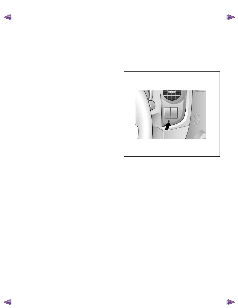
During the first 10 seconds:  
•  LED lights up; Test, switch - on delay 
•  LED rapidly flashes (2Hz); Door, bonnet, open or 

system fault 


After approx. 10 seconds:  
•  LED slowly flashes; System on (0.5Hz) 


RTU7Z0SH019101

Activating the anti-theft system 

1.  When the key switch is turned to the ACC position or 

removed from the starter switch.  

2.  Closing and locking all the doors by the keylock or 

remote key, and the engine hood will cause the 

indicator light to come on.  

3. Approximately 10 seconds later, the indicator light 

will slow flash. The anti-theft system is now in 

operation. 

Antitheft system alarm operating 
conditions 

When the antitheft system is engaged, the alarm will 
operate under the following condition; 


1.  Whenever some forcibly attempts to open a door, 

the engine hood without using the key. 

2.  Whenever someone unlocks a door with door lock 

knob. 

3. Whenever the engine hood release handle is 

operated. 


ANTITHEFT SYSTEM 11B-3 

Function of a keyless entry system 

With a keyless entry system the car can be locked or 
unlocked from any position around the car up to a 
specified distance, by using the potable radio remote 
transmitter inside key (remote key). 

Status LED 

While the system is in delay the alarm system is active 
and LED flashes at 0.5Hz with or without activated 
interior protection. 

Hazard relay 

The hazard warning lights will be activated by an 
external relay. The output is low active. 

Switches 

All switches to ground. This makes it possible for failure 
analysis to detect a short circuit or a broken wire to 
each switch. To use this feature it is necessary to place 
a 1.8k

Ω resistor in parallel to the required switch. 

Receiver 

The receiver is integrated into the control unit.  

To lower the idle current the receiver is equipped with a 
standby mode. The antenna is integrated on the printed 
circuit board. 

Depending on the mounting position of the control unit 
the antenna can be connected externally. 

Range of communication 

The range of communication between remote key and 
receiver is intended to be least 3 m from centre of the 
car. 


Diagnosis 

For diagnostic purpose the communication with an 
internal diagnostic device ( Tech-2 ) is possible. 


901RW176

Transmitter (into remote key) 

•  Electronics integrated in remote key container for 

TFR/TFS. 

•  Antenna integrated in remote key container. 
•  Frequency band is 433.92 MHz. 
•  Two function buttons (Door lock/Door unlock) 
•  Two status LED for TF (Door lock/Door unlock) 


OM


11B-4 ANTITHEFT SYSTEM 

Transmitter (into remote key) power 

The transmitted power is less than 10 m W. 

Battery life time for transmitter power 

The minimum life time of battery is 2 years with 15 
lock/unlock cycles per day. 

While the battery is changed, the data retention will be 
at least 3 minutes without pressing a button. 

Super lock 

(Mechanical anti-theft locking system) 

To Lock: 

All doors must be closed; press the lock button on the 
remote control unit again within 10 seconds after 
locking or turn key in driver's door lock towards rear of 
vehicle again within 10 seconds after locking, then turn 
it back to the vertical position and remove. 

Lock buttons on all doors are positioned such that doors 
cannot be opened. 

To unlock: 

Press unlock button on remote key or turn key in 
driver's door lock towards front of vehicle, then turn it 
back to the vertical position and remove. If the key is 
used, antitheft alarm sound operate which continues 
until ignition switch turn ON. If a problem is found, open 
the driver door as necessary. 


No proper transmitter is available, what 
should be done for the system? 

When any proper transmitter is not available, a new 
transmitter should be programmed. Up to 5 transmitters 
can be provided with a scan tool (Tech-2) and by proper 
procedure.   

In addition to the absence of proper transmitter, it may 
happen particular secret code to the particular vehicle is 
missing. ln this case, the secret code must be provided 
by your organization. 

Otherwise transmitter cannot be programmed in any 
way. 

lf the essential for a scan tool (Tech-2) for programming 
and proper  software for Tech-2 are not available, there 
is no permanent way to fix system. Temporary replace 
with new ACU, new ICU and new transmitter without 
any secret code can make the system be deactivated, 
but it does not last long. Such a replacement does not 
solve any condition. Even after replacement, the system 
is activated automatically in short time and then no 
operation of the vehicle can be made in any way.  

Tech-2 should be provided in your organization. 

 
•  Security code management 
Your organization must keep security codes for all 
vehicles as confidential data. Once the security codes 
are lost, anybody who have the security code can 
access antitheft system. Your organization has 
responsibility of any missing vehicles caused by stolen 
security code. 

 
•  Essential tool (Scan tool: Tech-2) 
Your dealership must have Tech-2, and Tech-2 updated 
software for immobilizer system. 


ANTITHEFT SYSTEM 11B-5 

Diagrams and Schematics 

System Wiring Diagrams 


RAW4C0XF000101 


Content   ..  1487  1488  1489  1490   ..