Isuzu KB P190. Manual - part 1356


  Index      Isuzu     Isuzu KB P190 - service repair manual 2007 year


Search            


Content   ..  1354  1355  1356  1357   ..


Isuzu KB P190. Manual - part 1356


8A-486  ELECTRICAL-BODY AND CHASSIS 

TROUBLE SHOOTING 

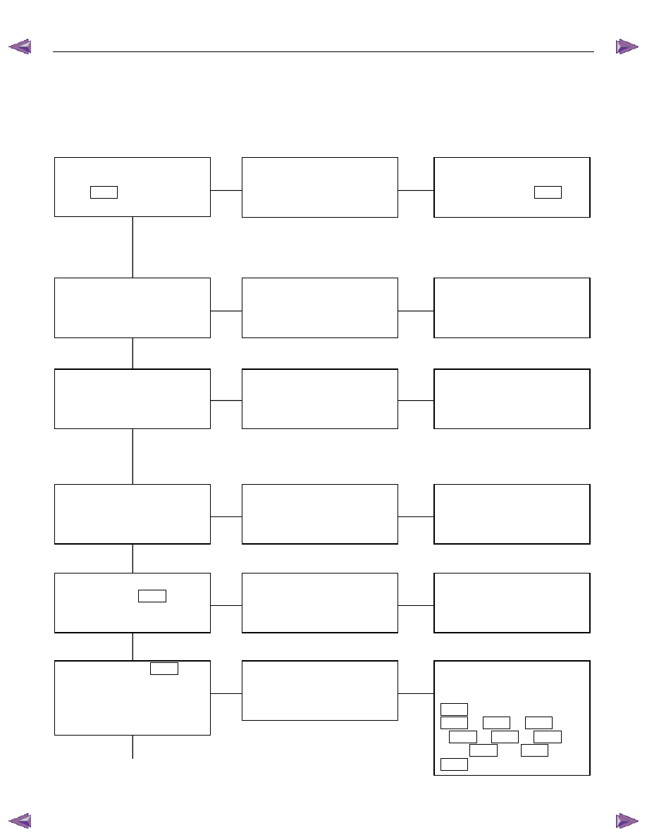
Rear defogger inoperative 


Checkpoint  

Trouble 

Cause 


Countermeasure 


Reinstall or replace the fuse 
No. C7 (10A) and 9  

B56


Poor fuse contact or blown 


NG 


Reinstall or replace the fuse 

C18 (20A) 


C18 (20A, Fuse box) 


Poor fuse contact or blown 


Replace the rear defogger 

switch 


Rear defogger switch function 


Switch malfunction 


NG 

NG 

OK 

OK 

OK 

 
Fuse No. C3 (10A, Fuse box)  
and 9  

B56 


Replace the rear defogger 

relay 


Relay malfunction 


NG 

Continued on the next page 


Rear defogger relay function 


Repair grounding point contact


Grounding point  

C2 


Poor grounding point contact 


NG 

OK 

Repair open circuit or poor 
connector contact between 
fuse No. C3 (10A) and 3 
 

B7 

, C18 (20A) and 1 


B7 

, 2  

B7 

 (3  

B55

) and 

1  

L4 

, 4  

B7 

 (3  

B54

and 3  

B46 

 or 1  

B46

 and 


C2 


Voltage between 1  

L4 

 - 

ground when the starter switch 
and the rear defogger switch 
are at on position (should be 
battery voltage present) 


Open circuit or poor connector 

contact 


NG 

OK 


ELECTRICAL-BODY AND CHASSIS  8A-487 

Checkpoint  

Trouble 

Cause 


Countermeasure 


OK 

Repair open circuit or 

connector contact between 1 


L7 

 and  

C2 


Open circuit or poor connector 

contact 


NG 

Continued from the previous page 

Continuity between 1  

L7 


and  

C2 


Repair heat wire 


Continuity between rear 

defogger terminals 


Broken heat wire of rear 

defogger 


NG 

OK 


8A-488  ELECTRICAL-BODY AND CHASSIS 


  REMOVAL AND INSTALLATION 


1


RTW77ASH000201 


REAR DEFOGGER SWITCH 

Removal 

1.  Instrument Panel Cluster Assembly 

•  Refer to Section 10 “BODY” for center cluster panel 

assembly removal steps. 

2.  Rear Defogger Switch (With HVAC control unit) (1) 


Refer to Section 1 “HVAC” HVAC control unit assembly

removal steps. 


Installation 

Follow the removal procedure in the reverse order to install the 
rear defogger switch. 


ELECTRICAL-BODY AND CHASSIS  8A-489 

  INSPECTION AND REPAIR 


Switch side 

B57 


REAR DEFOGGER SWITCH 

Rear Defogger Switch Connections 


Terminal No. 

SW position 

9 7 8 

ON 


OFF 


B7 

RTW78ASH002901 


REAR DEFOGGER RELAY 

Check continuity between the relay terminals. 

2

1

........................ No continuity 

(When battery voltage is applied between 

 and 

3

2

1

........................ Continuity 


INSPECTION OF REAR DEFOGGER HEAT 

WIRE 

•  Heat wires are printed on the inner side of glass. 
 

To clean, use a soft cloth and wipe horizontally along the

wires. 

•  Never use glass cleaner or equivalent. 
•  When measuring voltage, wind a piece of tin foil around the

tip of the negative probe and press the foil against the wire

with your finger as shown. 


(1) Turn the ignition switch on. 

(2) Turn the defogger switch on. 

(3) Measure the voltage between the three points on the heat 

wire and the (-) terminal with a voltmeter. 

(4) Check that the voltage becomes smaller from 

A

 to 

B

 to 

C

.


(5) If there is a place where the voltage suddenly changes to

0V, there is a broken wire between there and the power

side. 

(6) Move the tester probe from the position where the voltage

changes to 0V toward the power side and find where the

voltage suddenly increases. 


Content   ..  1354  1355  1356  1357   ..