Isuzu KB P190. Manual - part 1353


  Index      Isuzu     Isuzu KB P190 - service repair manual 2007 year


Search            


Content   ..  1351  1352  1353  1354   ..


Isuzu KB P190. Manual - part 1353


8A-474  ELECTRICAL-BODY AND CHASSIS 

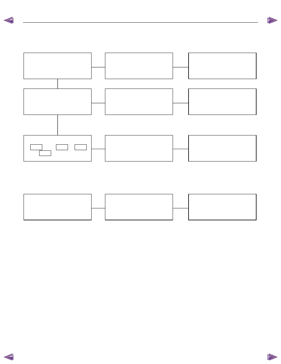
2.  Mirror on the right side does not operate 
 

Checkpoint  

Trouble 

Cause 


Countermeasure 


Replace the door mirror 

control SW. 


SW. malfunction 


NG 


Repair or replace the door 

mirror 


Mirror function on the left (or 

right) side 


Mirror malfunction on the left 

(or right) 


Repair open circuit or 
connector contact 
 

Continuity between 
7  

D19 

 and 2  

D7 

 (7  

D19


and 2  

D2 


Open circuit or poor connector 

contact 


NG 

NG 

OK 

OK 


Door mirror control SW. 

function 


3.  Mirrors on the both sides operate only in the vertical (or horizontal) direction 
 

Replace the door mirror

control SW.

SW. malfunction

NG

Door mirror control SW.

function


ELECTRICAL-BODY AND CHASSIS  8A-475 

4.  Mirror on the left side operates only in the vertical (or horizontal) direction 
 

Checkpoint  

Trouble 

Cause 


Countermeasure 


Replace the door mirror 

control SW. 


SW. malfunction 


NG 


Repair or replace the door 

mirror 


Door mirror function 


Door mirror malfunction 


Repair open circuit or 
connector contact 
 

Continuity between 
4  

D19 

 and 4  

D7 

 (10 


D19 

 and 1  

D2 


Open circuit or poor connector 

contact 


NG 

NG 

OK 

OK 


Door mirror control SW. 

function 


5.  Mirror on the right side operates only in the vertical (or horizontal) direction 


Replace the door mirror 

control SW. 


Door mirror control 

malfunction 


NG 


Repair or replace the door 

mirror 


Door mirror function 


Door mirror malfunction 


Repair open circuit or 
connector contact 
 

Continuity between 
4  

D19 

 and 4  

D2 

 (10 


D19 

 and 1  

D2 


Open circuit or poor connector 

contact 


NG 

NG 

OK 

OK 


Door mirror control SW. 

function 


8A-476  ELECTRICAL-BODY AND CHASSIS 


  REMOVAL AND INSTALLATION 


DOOR MIRROR CONTROL SWITCH 

Removal 

1.  Disconnect the battery ground cable. 

2.  Door trim pad Assembly 

•  Refer to section 10 “BODY” for door trim pad assembly 

removal steps. 

3.  Door Mirror Control Switch 


Remove the power window switch bezel. 
•  Remove the screw. 
•  Disconnect the switch connector. 
•  To remove the switch panel assembly. 


Installation 

To install, follow the removal steps in the reverse order. 


DOOR MIRROR 

Removal and Installation 

Refer to the DOOR MIRROR in section 10 “BODY”. 


ELECTRICAL-BODY AND CHASSIS  8A-477 

  INSPECTION AND REPAIR 


Switch side 

D19 


Door Mirror Control Switch 

1.  Switch side Connector Circuit 

  Check continuity between the switch connector terminals

while operating the door mirror control switch as shown in 

the following table. 


RTW48AMF000601 

MV, MH, b, and e terminals have internal connections (circuitry).  
4-point switch (Will not operate at intermediate positions.) 


Harness side 

D19 


2.  Harness Side Connector Circuit 

  Remove the connector No.  

D19 

 of the mirror control 

switch and check voltage and continuity of the harness side

connector. 
•  When there is no continuity at the terminal No. 2, 3, 9

and 10, it is considered that the circuit with terminal No. 

7 (W/B) is defective. 


Content   ..  1351  1352  1353  1354   ..