Isuzu KB P190. Manual - part 1203


  Index      Isuzu     Isuzu KB P190 - service repair manual 2007 year


Search            


Content   ..  1201  1202  1203  1204   ..


Isuzu KB P190. Manual - part 1203


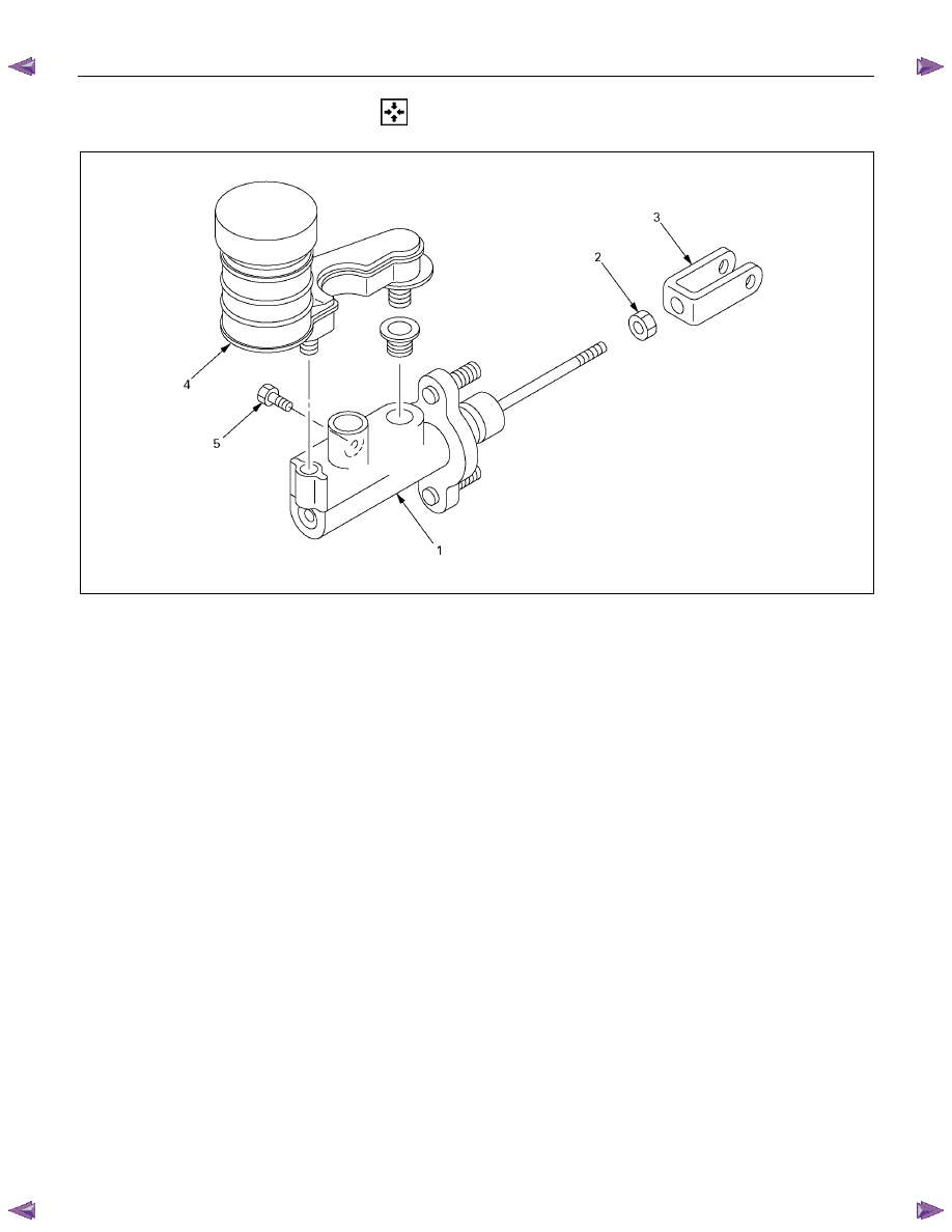
7C-34  CLUTCH 

  REASSEMBLY 


Reassembly Steps 


1. Body sub assembly 


2. Lock nut 

 3. 

Yoke 


4. Reservoir tank 


5. Bolt : Reservoir Tank 


CLUTCH  7C-35 

SLAVE CYLINDER (MSG, MUA) 

  DISASSEMBLY 


Disassembly Steps 

▲ 1. Boot 
 

2. Push rod 


3. Piston and piston cup 


 4. 

Spring 


5. Cylinder body 


Important Operations 

1. Boot 
Brake fluid spilled on painted or plastic surfaces will cause 
serious damage. 
Take care not to spill brake fluid. 


7C-36  CLUTCH 

  INSPECTION AND REPAIR 

 
Make the necessary adjustments, repairs, and part replacements if excessive wear or damage is discovered during 
inspection. 


Cylinder Body 

1.  Clean the cylinder body. 

2. Check the fluid return port for restrictions and clean it if 

necessary. 


Cylinder Bore and piston Clearance 

1.  Clean the cylinder body and the piston. 

2.  Use an inside dial indicator to measure the cylinder bore. 

3.  Use a micrometer to measure the piston diameter. 

4.  Calculate the clearance between the cylinder bore and the

piston diameter. 


If the clearance exceeds the limit, the entire slave cylinder

assembly must be replaced. 

Cylinder Bore and Piston Clearance 

mm(in)

Standard

Limit

0.07 (0.0028)

0.15 (0.006)


Piston and Piston Cup 

Visually inspect the disassembled piston and piston cup for 
excessive wear and damage. 
Replace the inner parts with new parts (Repair kit A) shown in 
the illustration. 


CLUTCH  7C-37 

  REASSEMBLY 


Reassembly Steps 

▲  1. Cylinder body 
 2. 

Spring 

▲  3. Piston and piston cup 


4. Push rod 

 5. 

Boot 


Important Operations 

1. Cylinder Body 

1)  Clean the cylinder body. 

2)  Apply brake fluid to the cylinder bore. 


3.  Piston and piston Cup 

1)  Apply brake fluid to the piston and piston cup. 

2)  Install the cups to the piston. 

  Note the installation direction of the piston cups in the

illustration. 

3) Install the piston and piston cup to the cylinder body. 


Content   ..  1201  1202  1203  1204   ..