Isuzu KB P190. Manual - part 1186


  Index      Isuzu     Isuzu KB P190 - service repair manual 2007 year


Search            


Content   ..  1184  1185  1186  1187   ..


Isuzu KB P190. Manual - part 1186


 Manual Transmission (MUX)    7B1-25

8. Install the counter middle roller bearing outer race,

counter shaft assembly and 5th counter gear to the
intermediate plate.

• Apply engine oil to the gear internal surface.

9. Install the 3rd counter gear.

• Apply engine oil to the gear internal surface.

10. Iinstall the 3rd input gear needle bearing.

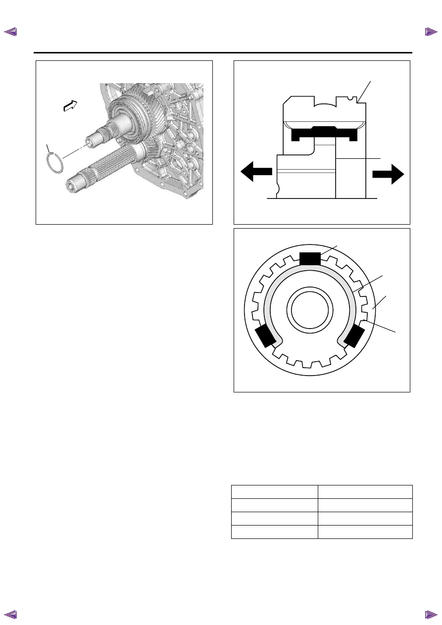
11. Assemble the 3rd-4th synchronizer assembly by

performing the following steps.

• Turn the clutch hub face (2) toward the sleeve

groove (1) (rear side) on the outer
circumference.

• Check that the inserts (3) fit snugly into the

clutch hub (6) ring insert grooves.

• Check that the inserts springs (4) are fitted to

the inserts as shown in the figure.

• Check that the clutch hub (6) and the sleeve (5)

slide smoothly.

• The insert springs (4) must be set in such a way

that the opening of spring faces different
direction.

12. Install the 3rd input gear assembly, 3rd-4th block

ring of 3rd input gear side, and 3rd-4th
synchronizer assembly.

• Apply engine oil to the gear internal surface.

13. Install the new 3rd-4th hub snap ring (1).

• Never reinstall the used snap ring.

• Choose the thickest snap ring among ones

whitch can be assembled.

Snap Ring Availability

RTW77BSH005101

1

Thickness

Identification color

1.9 mm(0.075 in)

No color

2.1 mm(0.083 in)

Yellow

2.3 mm(0.091 in)

Pink

1

2

LNW25CSH025601

3

4

5

6

LNW25CSH025701

7B1-26    Manual Transmission (MUX) 

14. Install the plate spring.

Notice:
Painted identification color (Blue) side to be
Transmission rear side.

Legend

1. Transmission rear side
2. Painted area of identification color (Blue)


15. Install the 3rd-4th block ring of output shaft side.

16. Install the output counter gear.

• Apply engine oil to the gear internal surface.

17. Install the new counter end snap ring (1).

• Never reinstall the used snap ring.

• Choose the thickest snap ring among ones

whitch can be assembled.

Snap Ring Availability

18. Use the installer 5-8840-2346-0 (1) to install the

new rubber seal.

• Never reinstall the used rubber seal.

• When seal press fitted, clearance not exists

between lip and end surface of gear.

19. Install the pilot bearing spacer.

20. Install the pilot bearing.

• Apply grease (BESCO L-2 or equivalent) to the

bearing roller.

21. Install the output shaft assembly.

22. Install the 3rd-4th shift arm assembly.

23. Install the 5th-reverse shift block assembly.

24. Install the 5th shift arm.

25. Install the 3rd-4th-5th shift rod.

26. Install the new 3rd-4th-5th shift rod snap ring (1).

• Never reinstall the used snap ring.

Thickness

Identification color

2.3 mm(0.091 in)

Pink

2.5 mm(0.098 in)

White

RTW77BSH005001

1

RTW77BSH008801

1

2

2.7 mm(0.106 in)

Green

Thickness

Identification color

RTW77BSH005201

1

RTW77BSH003601

1

 Manual Transmission (MUX)    7B1-27

27. Install the 5th shift arm new spring pin.

• Never reinstall the used spring pin.

Notice:
The spring pin must be drive in to this hole end surface
surfly.

28. Install the reverse shift arm.

29. The shift block lever is put into the dent of the 3rd-

4th-5th shift rod.

Legend

1. 3rd-4th-5th shift rod
2. Dent of 3rd-4th-5th shift rod
3. 5th-reverse shift block
4. Reverse shift rod
5. Shift block lever
6. 123.5 mm (4.86 in)


30. Install the reverse shift rod.

Notice:
The dents (1) of the shift rod should face outside of the
transmission so that the detent of the front case fits
them when reassembled.

31. Install the new reverse shift rod snap ring (1).

• Never reinstall the used snap ring.

32. Install the reverse shift arm new spring pin.

• Never reinstall the used spring pin.

Notice:
The spring pin must be drive in to this hole end surface
surfly.

33. Install the 1st-2nd shift arm (1).

RTW77BSH004901

1

RTW77BSH004801

1

6

2

5

4

3

RTW77BSH005301

1

RTW77BSH004701

1

7B1-28    Manual Transmission (MUX) 

34. Install the shift rod (2) with the 1st-2nd shft block

(3).

35. Install the 1st-2nd shift arm new spring pin.

• Never reinstall the used spring pin.

Notice:
The spring pin must be drive in to this hole end surface
surfly.

36. Install the control rod assembly (1).

37. Install the shift & select rod assembly (1) and bolts

temporarily.

38. Install the shift rod bracket (1) and bolts

temporarily.

39. Install the bolts to the shift & select rod assembly

and shift rod bracket.

• Tighten the shift & select rod bolts and the shift

rod bracket bolts to the specified torque.

Torque: 25 N

⋅m (2.5 kgf⋅m/18 lb⋅ft)

40. Install the counter 2nd gutter (4) and counter 5th

gutter (2).

• Tighten the gutter bolts to the specified torque.

Torque: 9 N

⋅m (0.9 kgf⋅m/78 lb⋅in)

41. Install the new front gutter (1) and new rear gutter

(3).

• Never reinstall the used gutters.

RTW77BSH008001

3

2

1

RTW77BSH007901

1

RTW77BSH007801

1

RTW77BSH007701

1


Content   ..  1184  1185  1186  1187   ..