Isuzu KB P190. Manual - part 1176


  Index      Isuzu     Isuzu KB P190 - service repair manual 2007 year


Search            


Content   ..  1174  1175  1176  1177   ..


Isuzu KB P190. Manual - part 1176


7B1-98     MANUAL TRANSMISSION 


226RS031

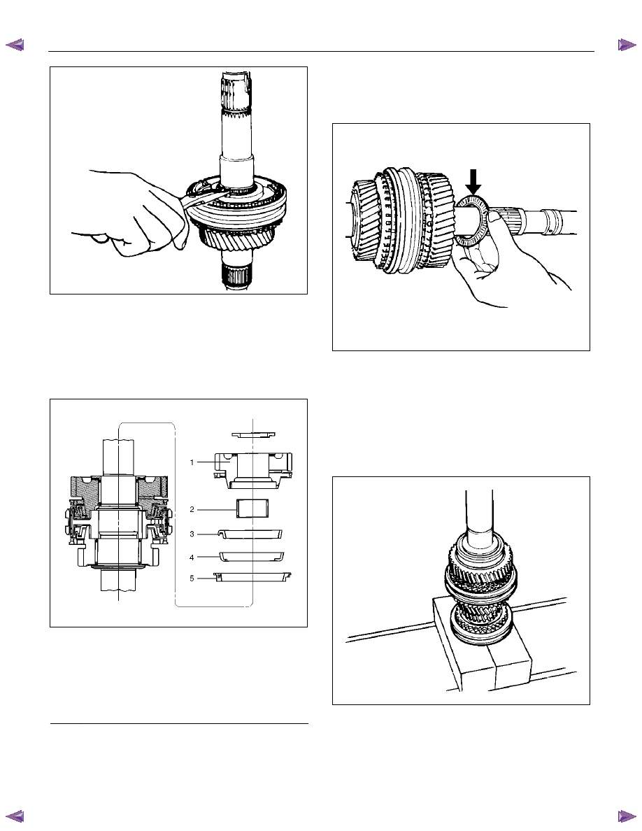
  9. Install the needle bearing, 1st block ring, 1st outside

ring, 1st inside ring, and 1st gear. 
•  Apply engine oil to the needle bearing, 1st gear

thrust surfaces and synchronizer ring friction
surfaces. 

•  The 1st gear dog teeth must be facing the

transmission front side. 


226RS053


Legend 

(1) 1st 

Gear 

(2) Needle 

Bearing 

(3) Inside 

Ring 

(4) Outside 

Ring 

(5) Block 

Ring 


 10. Install the 1st gear thrust bearing and the race to the 

main shaft. 

The thrust bearing side must be facing the 
transmission front side. 


226RS054

 11. Apply engine oil to the mainshaft ball bearing and 

the mainshaft. 

Install the ball bearing and needle bearing collar to 
the mainshaft. 

The ball bearing snap ring groove must be facing 
the transmission rear side. 

Use a bench press and installer 9-8522-1165-0 to 
slowly force the collar into place. 


226RS055


MANUAL TRANSMISSION     7B1-99 

 12.  Apply engine oil to the needle bearing and the 3rd

gear thrust surfaces. 

Install the needle bearing and the 3rd gear to the
mainshaft. 

The 3rd gear dog teeth must be facing the
transmission front side. 


226RS056

 13. Install the 3rd block ring. 

 14. Check and install the 3rd-4th synchronizer assembly

by using the following steps: 

1.  Check that the inserts (3) fit snugly into the

clutch hub insert grooves. 

2.  Check that the insert springs (4) are fitted to the

inserts as shown in the illustration. 

3.  Check that the clutch hub (5) and the sleeve (6) 

slide smoothly. 

4. Install the synchronizer assembly to the

mainshaft. 

The clutch hub face with the heavy boss must be

facing the 3rd gear side. 


226RS049


226RW221


15. Select and install mainshaft snap ring using the

following instructions: 

Select the snap ring which will provide the minimum 
clearance between the 3rd-4th clutch hub and the 
snap ring. 


226RS058

There are three snap ring sizes available. 

The snap rings are color-coded to indicate their 
thickness, as shown in the figure. 


7B1-100     MANUAL TRANSMISSION 


226RS021

Clutch Hub and Snap Ring Clearance 

Standard: 0 - 0.1 mm (0 - 0.004 in) 


Snap Ring Availability 

Thickness Color 

Coding 

1.80 mm (0.071 in) 

White 

1.85 mm (0.073 in) 

Yellow 

1.90 mm (0.075 in) 

Blue 

•  Use a pair of snap ring pliers to install the snap

ring to the mainshaft. 

The snap ring must be fully inserted into the
mainshaft snap ring groove. 


 16. Install the top block ring. 

Apply grease to the needle bearing inner and outer 
circumferences and install the needle bearing in the 
top gear shaft. 

 17. Use a bench press to install the top gear shaft ball 

bearing to the top gear shaft. 


226RS059

The snap ring groove of the ball bearing must be 
facing the transmission front side. 

 18. Use a pair of snap ring pliers to install the top gear 

shaft snap ring to the top gear shaft. 


MANUAL TRANSMISSION     7B1-101 

Main Data and Specifications 

General Specifications 
 

 MUA5G 

MUA5H 

MUA5S 

Transmission type 

Fully synchronized forward and reverse gears 

Control method 

Remote control with the gear shift lever on the floor. 

Gear ratio: Transmission 

1st 

4.008 

4.008 

4.357 


2nd 

2.301 2.301 2.502 


3rd 

1.427 1.427 1.501 


4th 

1.000 1.000 1.000 


5th 

0.828 0.744 0.809 


Rev. 

3.651 3.651 3.970 

Transmission oil capacity 

2.95 lit. (3.12 US qt) 

Type of lubricant 

Engine oil: Refer to the chart in "SECTION 0" 


Content   ..  1174  1175  1176  1177   ..