Isuzu KB P190. Manual - part 1170


  Index      Isuzu     Isuzu KB P190 - service repair manual 2007 year


Search            


Content   ..  1168  1169  1170  1171   ..


Isuzu KB P190. Manual - part 1170


7B1-74     MANUAL TRANSMISSION 

 8. Apply molybdenum disulfide type grease to the

areas shown in the figure and install the shift fork.  

F07L100026

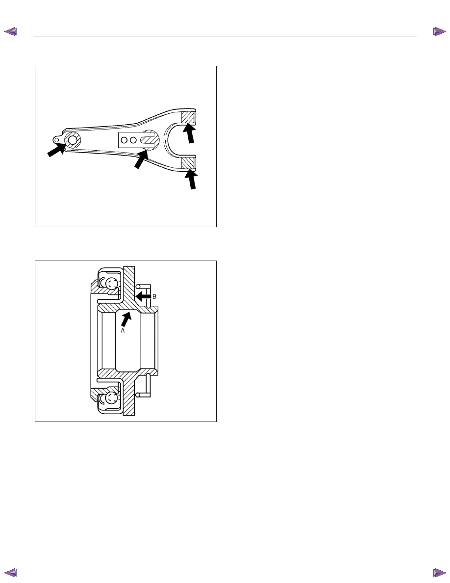
  9. Pack the inside recess (A) and coat the back (B) of

the release bearing with molybdenum disulfide type
grease, as shown in the figure. 

A07RW075

10. Install the release bearing on the front cover, joining

it to the shift fork. 


MANUAL TRANSMISSION     7B1-75 

Intermediate Plate with Gear Assembly, Detent, Shift Arm, Shift Rod, and 

Interlock Pin 

Disassembled View 


RTW57BLF000201 

Legend 

(1)  Detent Spring Plate and Gasket 

(7) 1st-2nd Shift Rod 

(2)  Detent Spring 

(8) 3rd-4th Shift Rod 

(3)  Detent Ball 

(9) 3rd-4th Shift Arm 

(4)  Spring 

(10) 1st-2nd Shift Arm 

(5)  Rev-5th Shift Rod 

(11) Interlock Pin 

(6)  Rev-5th Shift Arm and Reverse Inhibitor 

(12) Intermediate Plate and Gear Assembly 


7B1-76     MANUAL TRANSMISSION 

Disassembly 

  1. Remove the detent spring plate and gasket, detent

spring and detent ball. 

Use a magnetic hand to remove the detent balls
from the intermediate plate. 


220RS011

  2. Remove the spring. 

  3. Remove the rev-5th shift rod, and rev-5th shift arm

and the reverse inhibitor. 

Remove the 1st-2nd shift rod, 3rd-4th shift rod, 3rd-
4th shift arm, and 1st-2nd shift arm. 
•  Hold a round bar against the shift rod end. 


230RS003

•  Use a spring pin remover to remove the shift

arm spring pins from the shift arms and the shift
rods. 


230RS0004

•  Be careful not to lose the interlock pins, when 

pulling out the shift rod rearward. 

The interlock pins are located between the 
shifter rods in the intermediate plate. 


230RS0005

•  Remove the rev-5th, 1st-2nd and 3rd-4th shift 

rods carefully. 

 4. Remove the interlock pin from intermediate plate 

and gear assembly. 


MANUAL TRANSMISSION     7B1-77 

Inspection and Repair 

Make the necessary adjustments and part replacements
if excessive wear or damage is discovered during
inspection. 

Shift Arm Thickness 


• Use a micrometer to measure the shift arm

thickness. 

If the measured value is less than the specified limit,
the shift arm must be replaced. 


Shift Arm Thickness 

 Standard  Limit 

1st-2nd 

9.60 - 9.85 mm 

(0.378 - 0.388 in) 

3rd-4th 

Rev.5th 

9.60 - 9.80 mm 

(0.378 - 0.386 in) 

9.0 mm 

(0.354 in) 


230RS006

Detent Spring Free Length 


•  Use a vernier caliper to measure the detent spring

free length. 

If the measured value is less than the specified limit,
the detent spring must be replaced. 


Detent Spring Free Length 

Standard Limit 

26.8 mm (1.06 in) 

26.2 mm (1.03 in) 


SOUTH AFRICA 5th-Rev Only 

Detent Spring Free Length 

 Standard  Limit 

Outer 

27.6 mm (1.09 in) 

27.0 mm (1.06 in)

Inner 

26.6 mm (1.05 in) 

26.0 mm (1.02 in)


220RS012

Detent Spring Tension 


• Use a spring tester to measure the detent spring 

tension. 

If the measured value is less than the specified limit, 
the detent spring must be replaced. 


Detent Spring Tension 

Compressed height 

Standard 

20 mm (0.787 in) 

87.2 - 97.1 N 

(19.6 - 21.8 lb) 


220RS013


SOUTH AFRICA 5th-RV Only 

Detent Spring Free Length 

 Compressed Standard 

Outer 

20 mm (0.787 in) 

93.5 – 103.3 N 

 (21.0 – 23.3 lb) 

Inner 

20 mm (0.787 in) 

26.4 – 36.3 N 

 (5.9 – 8.2 lb) 


Content   ..  1168  1169  1170  1171   ..