Isuzu KB P190. Manual - part 114


  Index      Isuzu     Isuzu KB P190 - service repair manual 2007 year


Search            


Content   ..  112  113  114  115   ..


Isuzu KB P190. Manual - part 114


4B-12  REAR AXLE 

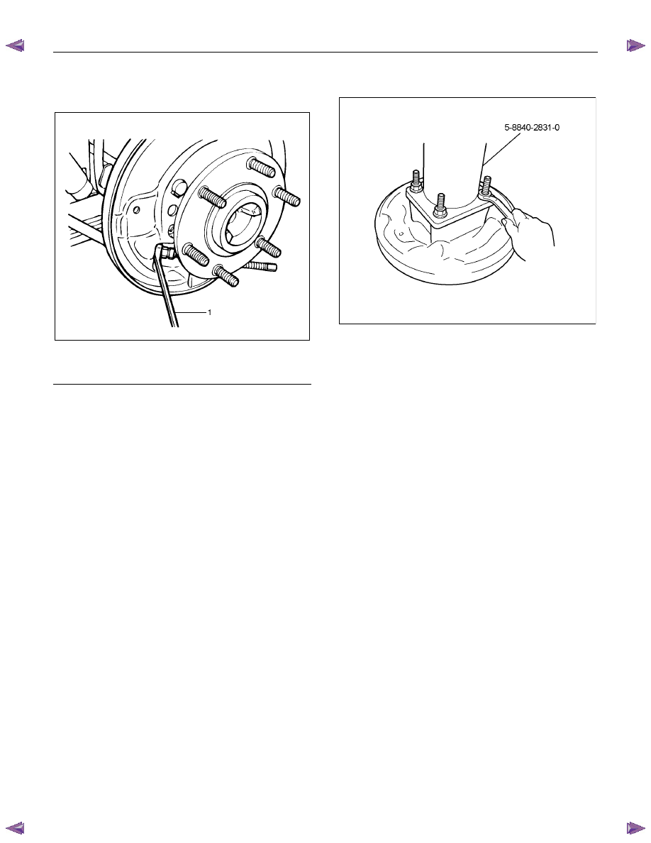
9.  Use offset box wrench to compress locking lugs

on the cable, then remove parking brake outer

cable from back plate. 


311RS012

Legend 

  1.  Offset Box Wrench 


10. Remove wheel cylinder. 

11. Remove bearing holder fixing nuts. 

12. Take out axle shaft assembly with back plate and

set it on a bench press as following illustration. 


When axle shaft is extracted, since axle case oil

seal is damaged, replace the axle case oil seal. 

13. Remove snap ring. Use snap ring pliers to

remove. Snap ring is prohibition of reuse. 

14. Remove shim (If so equipped) 

15. Grind the retainer surfaces using a grinder, then

chisel them out with a chisel. 


16. Position remover 5-8840-2831-0 on the bearing 

holder with 4 nuts. 


RTW54BSH000801


REAR AXLE  4B-13 

17. Remove double taper roller bearing, oil seal,

bearing holder, and back plate from axle shaft by

means of a press. 
•  Discard used oil seal, double taper roller 

bearing, snap ring, retainer. 


RTW54BMH000201

Legend 

  1.  Bench Press Fitting 

 2. Axle 

Shaft 


18. Oil seal is removed from bearing holder. 


19. 

Bearing outer race is removed from bearing 

holder. 
•  When it cannot remove by hand, bearing 

outer race is removed using installer 5-8840-

2119-0 and grip 5-8840-0007-0. 


RTW54BSH000701


20. 

Remove differential assembly fixing bolts and 

nuts and take out differential assembly. 
•  φ194mm differential assembly has three kinds 

of bolts. 


Note the installation holes. 

21. Remove wheel pin from axle shaft, using the 

remover 5-8840-0079-0. 

420L100009

22. Remove axle case oil seal. 

•  Discard used oil seal. 


4B-14  REAR AXLE 

Inspection and Repair 

Make all necessary adjustments, repairs, and part
replacements if wear, damage, or other problems are
discovered during inspections. 

Visual Check 

Inspect the following parts for wear, damage or other
abnormal conditions. 

•  Axle Shaft 

Axle Shaft 

When checking the axle shaft, pay special attention to
the splined portions and replace the shaft if distortion
or step wear is noticeable.  Correct slight step wear
with a pencil grinder. 


420RS008

Axle Shaft Run-Out 

Check the shafts for bending with the use of a dial
indicator in contact with the shaft.  Rotate the shaft
slowly and observe the dial indicator. 

Limit mm 

(in)

1.0 (0.039) 

Note : 
Never use heat to correct bending. 


RTW74BSH000101

Legend 

    a. 350 mm (13.8 in) 


Axle Shaft Flange Run-Out 

Check the axle shaft flange for run-out.  Hold the 
probe of a dial indicator in contact with the flange. 
Rotate the shaft slowly and observe the dial. 

Limit mm 

(in)

0.08 (0.003) 


RTW74BSH000201

Legend 

    b. 160 mm (6.3 in) 


REAR AXLE  4B-15 

Reassembly 

1. Using the oil seal installer 5-8840-2202-0 and 

grip 5-8840-0007-0, install new axle case oil seal.


RTW54BSH000301


Note : 
Confirm  that the dimension : A should be 34.5 – 
36.1 mm (1.36 – 1.42 in) 


A03R300004


2.  Install new oil seal in bearing holder, using the oil

seal installer 5-8840-2404-0. 


RTW54BSH000501

Legend 

    1. Oil Seal 

    2. Bearing Holder 


3. Drive wheel pin into axle shaft flange, using a 

hammer. 

4. Differential assembly 

a. Clean the mating surface of axle case and 

differential carrier. 

b.  Apply Three Bond 1215 (TB1215) or 

equivalent on the surface of differential 

assembly as flowing illustration. 


RTW74BSH000301

Legend 

    a. 3 mm (0.12 in) 


c.  Tighten bolts and nuts to the specified torque.


Content   ..  112  113  114  115   ..