Content .. 1125 1126 1127 1128 ..
Isuzu KB P190. Manual - part 1127
UNIT REPAIR (JR405E) 7A4-31
Reassembly steps
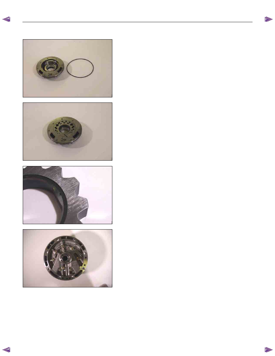
15PUMP18
1. O-ring (small)
Install new O-ring (small) to the oil pump housing.
16PUMP29
2. Outer rotor
3. Inner rotor
Install the outer rotor and the inner rotor to the oil pump
housing.
17PUMP42
NOTE:
The identification mark on the inner rotor must be facing
the inside of the oil pump housing.
18PUMP07
4. Oil pump cover
5. Oil pump housing
Install the oil pump cover to the oil pump housing.
Tighten the 8 bolts to the specified torque.
Torque: 9 N
⋅⋅⋅⋅m (0.9 kgf⋅⋅⋅⋅m/78 Ib⋅⋅⋅⋅in)
6. O-ring (large)
Install the O-ring (large) to the oil pump cover.
7. Seal ring
Install the 4 seal rings to the oil pump cover.