Isuzu KB P190. Manual - part 1050


  Index      Isuzu     Isuzu KB P190 - service repair manual 2007 year


Search            


Content   ..  1048  1049  1050  1051   ..


Isuzu KB P190. Manual - part 1050


UNIT REPAIR (AW30–40LE)

7A4–65

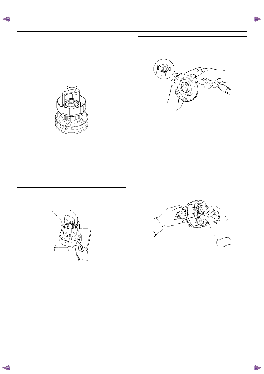
5. Place special tool on the spring retainer and

compress the return spring.
Using snap ring pliers, remove the snap ring.
Spring compressor : 5-8840-0254-0

248RY00003

6. Remove the piston return spring.

7. Place the forward clutch drum onto the OD support.

Holding the forward clutch piston by hand, apply
compressed air to the OD support to remove the
forward clutch piston.

248RY00042

8. Remove the O-rings from piston.

9. Remove the O-ring from forward clutch drum.

10. Remove the oil seal rings and thrust bearing from

forward clutch drum.

Inspection and Repair

1. Check forward clutch piston

Check that check ball is free by shaking the piston.
Check that the valve does not leak by applying
low-pressure compressed air.

248RY00031

2. Check forward clutch drum bushing.

Using a dial indicator, measure the inside diameter
of the forward clutch drum bushing.

Maximum inside diameter: 24.08mm (0.948in)

If the inside diameter is greater then the maximum,
replace the forward clutch drum.

248RY00043

3. Check disc, plate and flange.

Check to see if the sliding surface of the disc, plate
and flange are worn or burnt. If necessary, replace
them.

• If the lining of the disc is peeling off or discolored,

or even if parts of the printed numbers are
defaced, replace all discs.

7A4–66

UNIT REPAIR (AW30–40LE)

• Before assembling new discs, soak them in ATF

for at least fifteen minutes.

248RY00045

4. Check piston return spring.

Using calipers, measure the free length of the return
spring.

Standard length: 19.47 mm (0.7665in)

247RY00034

Reassembly

1. Coat the assembled thrust bearing and race with

petroleum jelly and install it onto the forward clutch
drum, with the race side facing downward.
Bearing and race (Reference)

248RY00044

2. Coat the three oil rings with ATF.

Contract the oil seal rings as shown, and install
three oil seal rings onto the forward clutch drum.

NOTE:  Do not spread the ring ends more than
necessary.

248RY00046

Inside diameter

33.7mm (1.327in)

Outside diameter

47.8mm (1.882in)

UNIT REPAIR (AW30–40LE)

7A4–67

3. Coat a new O-ring with ATF and install O-ring on the

forward clutch drum.

248RY00047

4. Coat new O-rings with ATF and install two O-rings

on the forward clutch piston.

5. Being careful not to damage the O-rings, press the

forward clutch piston into the forward clutch drum.

248RY00049

6. Install piston return spring.

248RY00065

7. Place special tool on the spring retainer, and

compress the return spring.
Spring compressor: 5-8840-0254-0
Install the snap ring with snap ring pliers. 
Be sure the end gap of the snap ring is not aligned
with the spring retainer claw.

248RY00003

7A4–68

UNIT REPAIR (AW30–40LE)

8. Install cushion plate rounded side down as shown.

248RY00069

9. Install five discs and five plates.

Install in order: P–D–P–D–P–D–P–D–P–D

10. And then install the flange, with the rounded edge

facing downward.

248RY00070

11. Install the snap ring with a screwdriver. 

Be sure the end gap of the snap ring is not aligned
with the cutout portion of the forward clutch drum.

248RY00041

12. Check piston stroke of forward clutch (C–1).

Using a dial indicator, measure the forward clutch
piston stroke by applying and releasing the
compressed air (380 – 780 kPa or 57 – 114 psi) as
shown.

Pack clearance: 0.6 – 1.0 mm (0.024 – 0.039 in)

If the piston stroke is not within specification,
replace the discs, and recheck the piston stroke.
Available flange sizes

248R200008

3.0mm (0.118in)

3.4mm (0.134in)

4.2mm (0.165in)

3.6mm (0.142in)

4.4mm (0.173in)

3.8mm (0.150in)

3.2mm (0.126in)

4.0mm (0.158in)


Content   ..  1048  1049  1050  1051   ..