Infiniti QX56 (JA60). Manual - part 970


  Index      Infiniti     Infiniti QX56 (JA60) - service repair manual 2010 year


Search            


Content   ..  968  969  970  971   ..


Infiniti QX56 (JA60). Manual - part 970


TM-182

< ON-VEHICLE REPAIR >

CONTROL VALVE WITH TCM

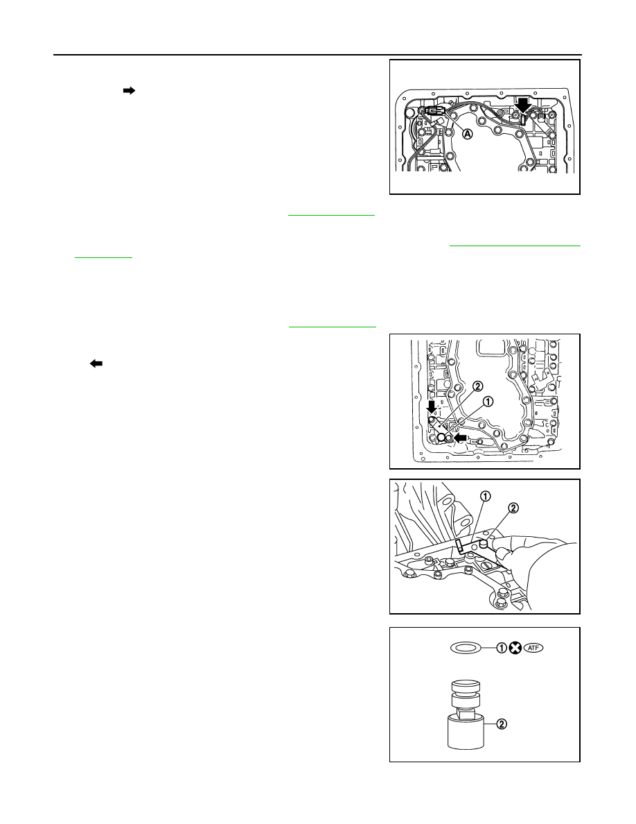
3. Connect A/T fluid temperature sensor 2 connector (A).
4. Securely fasten A/T fluid temperature sensor 2 harness with ter-

minal clip 

.

5. Install oil pan to transmission case. Refer to 

TM-170, "Oil Pan"

.

6. Connect the negative battery terminal.
7. Refill the A/T with fluid and check the fluid level and for fluid leakage. Refer to 

TM-148, "Checking the A/T

Fluid (ATF)"

.

REMOVAL AND INSTALLATION OF PLUG

Removal

1. Disconnect negative battery terminal.
2. Remove oil pan and oil pan gasket. Refer to 

TM-170, "Oil Pan"

.

3. Remove plug (1) with bracket (2) from control valve with TCM.

4. Remove bracket (1) from plug (2).

5. Remove O-ring (1) from plug (2).

Installation

CAUTION:

SCIA8125E

: Bolt

JSDIA1311ZZ

JSDIA1312ZZ

JSDIA1313ZZ

CONTROL VALVE WITH TCM

TM-183

< ON-VEHICLE REPAIR >

C

E

F

G

H

I

J

K

L

M

A

B

TM

N

O

P

After completing installation, check A/T fluid leakage and fluid level. Refer to 

TM-148, "Checking the A/

T Fluid (ATF)"

.

1. Install new O-ring (1) in plug (2).

CAUTION:

• Do not reuse O-ring.

• Apply ATF to O-ring.

• O-ring should be free of contamination.

2. Install plug (2) to bracket (1).

3. Install plug (1) [with bracket (2)] in control valve with TCM.

Tighten plug bolt (

) to the specified torque.

CAUTION:

Adjust bolt hole of bracket to bolt hole of control valve with

TCM.

4. Install oil pan to transmission case. Refer to 

TM-170, "Oil Pan"

.

5. Connect the negative battery terminal.
6. Refill the A/T with fluid and check the fluid level and for fluid leakage. Refer to 

TM-148, "Checking the A/T

Fluid (ATF)"

.

JSDIA1313ZZ

JSDIA1312ZZ

JSDIA1311ZZ

TM-184

< ON-VEHICLE REPAIR >

REAR OIL SEAL

REAR OIL SEAL

Rear Oil Seal

INFOID:0000000005148742

REMOVAL AND INSTALLATION

Removal

1. Remove rear propeller shaft. Refer to 

DLN-196, "Removal and Installation"

.

2. Remove transfer from transmission (4WD models). Refer to 

DLN-141, "Removal and Installation"

.

3. Remove rear oil seal using suitable tool.

CAUTION:

Do not scratch rear extension assembly (2WD models) or

adapter case assembly (4WD models).

Installation

1. Install new rear oil seal until it is flush into the rear extension

case (2WD models) using Tool or adapter case (4WD models)

using suitable tool.

CAUTION:

• Apply ATF to rear oil seal.

• Do not reuse rear oil seal.

2. Install transfer to transmission (4WD models). Refer to 

DLN-

141, "Removal and Installation"

.

3. Install rear propeller shaft. Refer to 

DLN-196, "Removal and

Installation"

.

4. Check the A/T fluid level and for fluid leakage. Refer to 

TM-148,

"Checking the A/T Fluid (ATF)"

.

SCIA5254E

Tool number

: ST33400001 (J-26082)

WCIA0475E

FLUID COOLER SYSTEM

TM-185

< ON-VEHICLE REPAIR >

C

E

F

G

H

I

J

K

L

M

A

B

TM

N

O

P

FLUID COOLER SYSTEM

Exploded View

INFOID:0000000005268405

Fluid Cooler

Removal and Installation

INFOID:0000000005268406

REMOVAL

1. Remove the radiator. Refer to 

CO-15, "Removal and Installation"

.

2. Disconnect the transmission fluid cooler hoses.
3. Remove the transmission fluid cooler.

INSTALLATION

Installation is in the reverse order of removal.

ALDIA0212GB

1.

Radiator

2.

Fluid cooler hose

3.

Fluid cooler

4.

Fluid cooler hose

5.

A/C condenser

Front


Content   ..  968  969  970  971   ..