Infiniti QX56 (JA60). Manual - part 623
INL-20
< COMPONENT DIAGNOSIS >
INTERIOR ROOM LAMP CONTROL CIRCUIT
2.
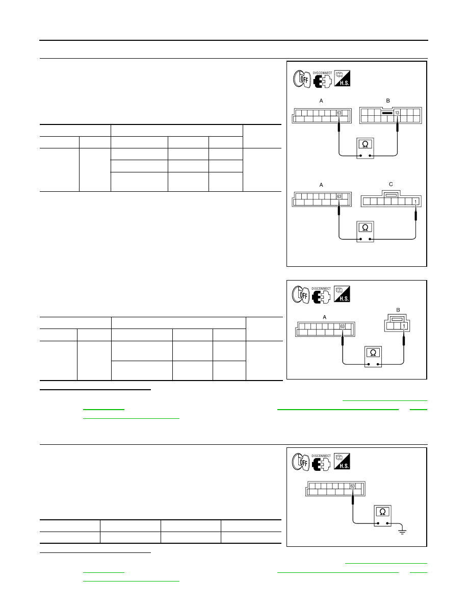
CHECK INTERIOR ROOM LAMP CONTROL OPEN CIRCUIT
1. Turn ignition switch OFF.
2. Disconnect BCM connector M20, door mirror connectors and
front room/map lamp assembly connector.
3. Check continuity between BCM connector M20 (A) terminal 63
and the door mirror connectors (B) and front room/map lamp
assembly connector (C).
4. Reconnect the front room/map lamp assembly connector.
5. Check continuity between BCM connector M20 (A) terminal 63
and the 2nd and 3rd row personal lamp connectors (B) terminal
1.
Is the inspection result normal?
YES
>> Check interior room lamps for an open. If OK, replace BCM. Refer to
. If NG, replace interior room lamp. Refer to
INL-77, "Removal and Installation"
.
NO
>> Repair the harness or connectors.
3.
CHECK INTERIOR ROOM LAMP CONTROL SHORT CIRCUIT
1. Turn ignition switch OFF.
2. Disconnect BCM connector M20, door mirror connectors and
2nd and 3rd row personal lamp connectors.
3. Switch the front room/map lamp assembly switch to ON posi-
tion.
4. Check continuity between BCM connector M20 terminal 63 and
ground.
Is the inspection result normal?
YES
>> Check interior room lamps for a short circuit. If OK, replace BCM. Refer to
. If NG, replace interior room lamp. Refer to
INL-77, "Removal and Installation"
.
BCM
Interior room lamp
Continuity
Connector
Terminal
Component
Connector
Terminal
M20 (A)
63
Door mirror LH
D4 (B)
13
Yes
Door mirror RH
D107 (B)
13
Front room/map
lamp assembly
R102 (C)
1
AWLIA0968ZZ
BCM
Interior room lamp
Continuity
Connector
Terminal
Component
Connector
Terminal
M20 (A)
63
Personal lamp 2nd
row
R203 (B)
1
Yes
Personal lamp 3rd
row
R205 (B)
1
ALLIA0412GB
Connector
Terminal
—
Continuity
M20
63
Ground
No
ALLIA0413GB