Infiniti QX56 (JA60). Manual - part 562


  Index      Infiniti     Infiniti QX56 (JA60) - service repair manual 2010 year


Search            


Content   ..  560  561  562  563   ..


Infiniti QX56 (JA60). Manual - part 562


GI-22

< FEATURES OF NEW MODEL >

IDENTIFICATION INFORMATION

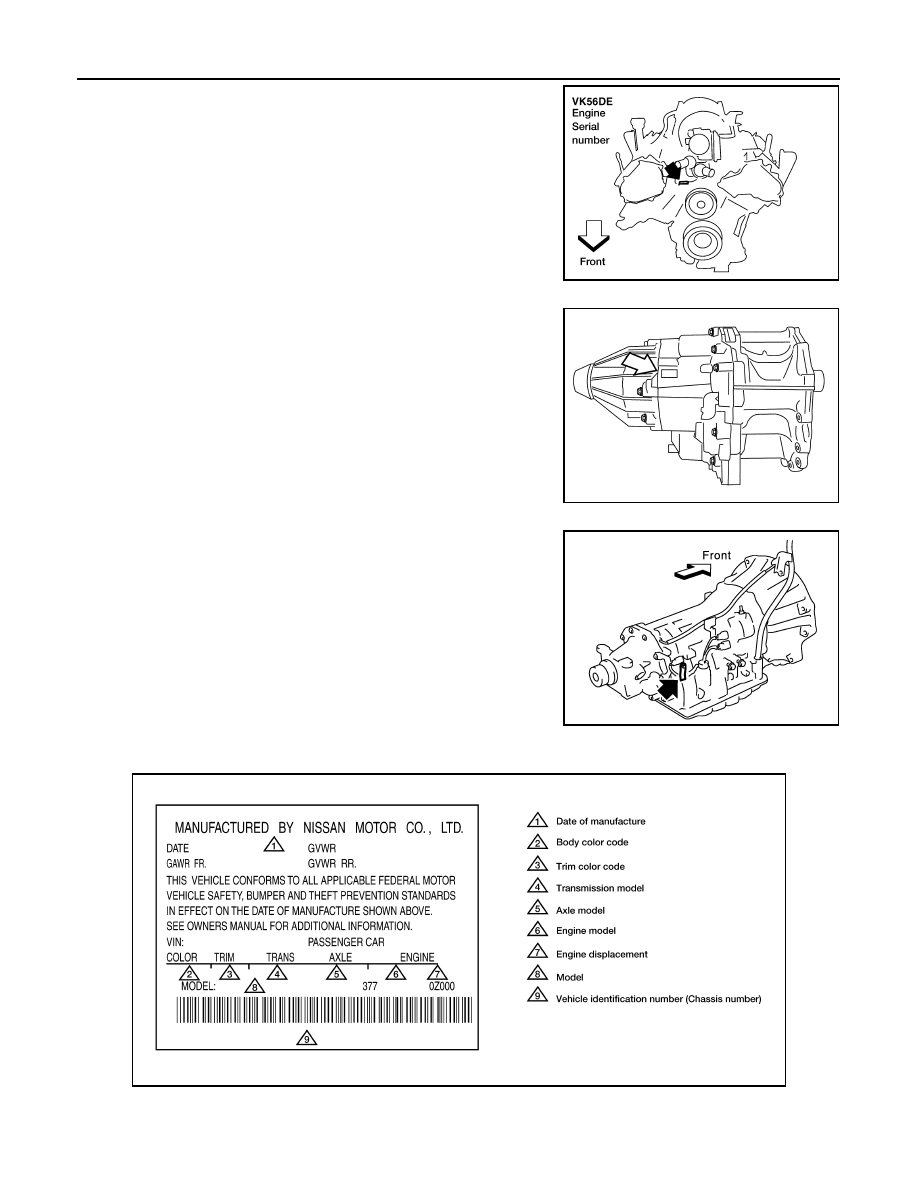
ENGINE SERIAL NUMBER

TRANSFER SERIAL NUMBER

AUTOMATIC TRANSMISSION NUMBER

Identification Plate

INFOID:0000000005149585

LAIA0044E

LAIA0048E

PAIA0054E

LAIA0027E

IDENTIFICATION INFORMATION

GI-23

< FEATURES OF NEW MODEL >

C

D

E

F

G

H

I

J

K

L

M

B

GI

N

O

P

Dimensions

INFOID:0000000005149586

Unit: mm (in)

Wheels & Tires

INFOID:0000000005149587

* With Steel Wheel

Drive type

2WD

4WD

Overall length

5254 (206.9)

5254 (206.9)

Overall width

2021 (79.6)

2021 (79.6)

Overall height (with roof rack)

1948 (76.7)

1968 (77.5)

Front tread width

1729 (68.1)

1729 (68.1)

Rear tread width

1729 (68.1)

1729 (68.1)

Wheelbase

3130 (123.2)

3130 (123.2)

Minimum Running Ground Clearance (at front suspension)

211.2 (8.3)

232 (9.1)

Drive Type

Grade

Road wheel

Tire

Spare tire size *

All

QX56

 20x8JJ Chromium Aluminum Alloy

P275/60R20

P275/60R20

       20X8J Steel

P275/60R20

P275/60R20

GI-24

< PRECAUTION >

PRECAUTIONS

PRECAUTION

PRECAUTIONS

Description

INFOID:0000000005149588

Observe the following precautions to ensure safe and proper servicing. These precautions are not

described in each individual section.

Precaution for Supplemental Restraint System (SRS) "AIR BAG" and "SEAT BELT 
PRE-TENSIONER"

INFOID:0000000005402047

The Supplemental Restraint System such as “AIR BAG” and “SEAT BELT PRE-TENSIONER”, used along

with a front seat belt, helps to reduce the risk or severity of injury to the driver and front passenger for certain

types of collision. This system includes seat belt switch inputs and dual stage front air bag modules. The SRS

system uses the seat belt switches to determine the front air bag deployment, and may only deploy one front

air bag, depending on the severity of a collision and whether the front occupants are belted or unbelted.

Information necessary to service the system safely is included in the SR and SB section of this Service Man-

ual.

WARNING:

• To avoid rendering the SRS inoperative, which could increase the risk of personal injury or death in

the event of a collision which would result in air bag inflation, all maintenance must be performed by

an authorized NISSAN/INFINITI dealer.

• Improper maintenance, including incorrect removal and installation of the SRS, can lead to personal

injury caused by unintentional activation of the system. For removal of Spiral Cable and Air Bag

Module, see the SR section.

• Do not use electrical test equipment on any circuit related to the SRS unless instructed to in this

Service Manual. SRS wiring harnesses can be identified by yellow and/or orange harnesses or har-

ness connectors.

PRECAUTIONS WHEN USING POWER TOOLS (AIR OR ELECTRIC) AND HAMMERS

WARNING:

• When working near the Airbag Diagnosis Sensor Unit or other Airbag System sensors with the Igni-

tion ON or engine running, DO NOT use air or electric power tools or strike near the sensor(s) with a

hammer. Heavy vibration could activate the sensor(s) and deploy the air bag(s), possibly causing

serious injury.

• When using air or electric power tools or hammers, always switch the Ignition OFF, disconnect the

battery, and wait at least 3 minutes before performing any service.

Precaution Necessary for Steering Wheel Rotation After Battery Disconnect

INFOID:0000000005259102

NOTE:

• This Procedure is applied only to models with Intelligent Key system and NATS (NISSAN ANTI-THEFT SYS-

TEM).

• Remove and install all control units after disconnecting both battery cables with the ignition knob in the

″LOCK″ position.

• Always use CONSULT-III to perform self-diagnosis as a part of each function inspection after finishing work.

If DTC is detected, perform trouble diagnosis according to self-diagnostic results.

For models equipped with the Intelligent Key system and NATS, an electrically controlled steering lock mech-

anism is adopted on the key cylinder.

For this reason, if the battery is disconnected or if the battery is discharged, the steering wheel will lock and

steering wheel rotation will become impossible.

If steering wheel rotation is required when battery power is interrupted, follow the procedure below before

starting the repair operation.

OPERATION PROCEDURE

1. Connect both battery cables.

NOTE:

Supply power using jumper cables if battery is discharged.

PRECAUTIONS

GI-25

< PRECAUTION >

C

D

E

F

G

H

I

J

K

L

M

B

GI

N

O

P

2. Use the Intelligent Key or mechanical key to turn the ignition switch to the 

″ACC″ position. At this time, the

steering lock will be released.

3. Disconnect both battery cables. The steering lock will remain released and the steering wheel can be

rotated.

4. Perform the necessary repair operation.
5. When the repair work is completed, return the ignition switch to the 

″LOCK″ position before connecting

the battery cables. (At this time, the steering lock mechanism will engage.)

6. Perform a self-diagnosis check of all control units using CONSULT-III. 

Procedures without Cowl Top Cover

INFOID:0000000005149591

When performing the procedure after removing cowl top cover, cover

the lower end of windshield with urethane, etc.

General Precautions

INFOID:0000000005149592

• Do not operate the engine for an extended period of time without

proper exhaust ventilation.

Keep the work area well ventilated and free of any inflammable

materials. Special care should be taken when handling any inflam-

mable or poisonous materials, such as gasoline, refrigerant gas,

etc. When working in a pit or other enclosed area, be sure to prop-

erly ventilate the area before working with hazardous materials.

Do not smoke while working on the vehicle.

• Before jacking up the vehicle, apply wheel chocks or other tire

blocks to the wheels to prevent the vehicle from moving. After jack-

ing up the vehicle, support the vehicle weight with safety stands at

the points designated for proper lifting before working on the vehi-

cle.

These operations should be done on a level surface.

• When removing a heavy component such as the engine or tran-

saxle/transmission, be careful not to lose your balance and drop

them. Also, do not allow them to strike adjacent parts, especially

the brake tubes and master cylinder.

PIIB3706J

SGI285

SGI231


Content   ..  560  561  562  563   ..