Infiniti QX56 (JA60). Manual - part 486


  Index      Infiniti     Infiniti QX56 (JA60) - service repair manual 2010 year


Search            


Content   ..  484  485  486  487   ..


Infiniti QX56 (JA60). Manual - part 486


EM-98

< DISASSEMBLY AND ASSEMBLY >

ENGINE UNIT

• Remove oil and dust on the crankshaft pin and surfaces of each

bearing completely. 

• Cut a plastigage slightly shorter than the bearing width, and place

it in the crankshaft axial direction, avoiding oil holes.

• Install the connecting rod bearings to the connecting rod and con-

necting rod bearing cap, and tighten the connecting rod bolts to the

specified torque. 

CAUTION:

Do not rotate crankshaft with plastigage installed.

• Remove the connecting rod bearing cap and bearings. Measure

the plastigage width using the scale on the plastigage bag.

NOTE:

The procedure when the measured value exceeds the repair limit is the same as that described in “Method

of Measurement”.

MAIN BEARING OIL CLEARANCE

Method of Measurement

• Install the main bearings to the cylinder block and main bearing

cap. Measure the main bearing inside diameter with the bearing

cap bolts tightened to the specified torque. Refer to 

EM-83, "Disas-

sembly and Assembly"

.

(Oil clearance) = (Inside diameter of main bearing) – (Crankshaft

journal diameter)

• If measured value exceeds the repair limit, select main bearings referring to the main bearing inside diame-

ter and crankshaft journal diameter, so that the oil clearance satisfies the standard. Refer to 

EM-101, "How

to Select Piston and Bearing"

.

Method of Using Plastigage

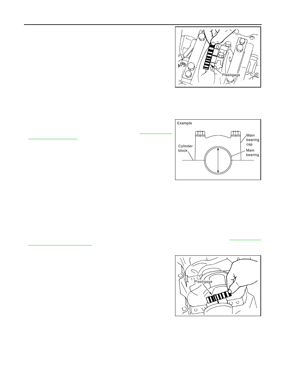
• Remove oil and dust on the crankshaft journal and surfaces of

each bearing completely. 

• Cut a plastigage slightly shorter than the bearing width, and place

it in crankshaft axial direction, avoiding oil holes.

• Install the main bearings to the cylinder block and main bearing

cap, and tighten the main bearing bolts to the specified torque. 

CAUTION:

Do not rotate crankshaft with plastigage installed.

• Remove bearing cap and bearings. Measure plastigage width

using the scale on the plastigage bag.

NOTE:

The procedure when the measured value exceeds the repair limit

is the same as that described in “Method of Measurement”.

CRUSH HEIGHT OF MAIN BEARING

KBIA2550E

Standard:

No. 1 and 5 journals

: 0.001 - 0.011 mm (0.00004 - 0.0004 in)

No. 2, 3 and 4 journals

: 0.007 - 0.017 mm (0.0003 - 0.0007 in)

Limit:

No.1 and 5 journals

: 0.021 mm (0.0008 in)

No. 2, 3 and 4 journals

: 0.027 mm (0.0011 in)

PBIC1644E

KBIA2551E

ENGINE UNIT

EM-99

< DISASSEMBLY AND ASSEMBLY >

C

D

E

F

G

H

I

J

K

L

M

A

EM

N

P

O

• When the bearing cap is removed after being tightened to the

specified torque with main bearings installed, the tip end of the

bearing must protrude. Refer to 

EM-83, "Disassembly and Assem-

bly"

 for the tightening procedure.

• If standard is not met, replace main bearings.

CRUSH HEIGHT OF CONNECTING ROD BEARING

• When connecting rod bearing cap is removed after being tightened

to the specified torque with the connecting rod bearings installed,

the tip end of the bearing must protrude. Refer to 

EM-83, "Disas-

sembly and Assembly"

 for tightening procedure.

• If standard is not met, replace connecting rod bearings.

MAIN BEARING CAP BOLT DIAMETER

• Check for bolts (M9 and M12) installed from lower side using the

following procedure.

NOTE:

• Side bolt (M10) is outside the target.

• Figure shows M12 bolt.

• Measure bolt diameter 

″d1″ from tip of the bolt to dimension "a".

• Measure bolt diameter 

″d2″ from the dimension between tip of the

bolt and dimension 

″b″ as base station to dimension ″c″.

NOTE:

 If a narrower part in the threads is determined by visual check,

measure 

″d2″ at that point.

• Calculate the difference between 

″d1″ and ″d2″.

M9 bolt

M12 bolt

• Replace applicable bolts if outside the limit.

CONNECTING ROD BOLT DIAMETER

• Measure diameter 

″d″ at position shown.

Standard

: There must be crush height

SEM502G

Standard

: There must be crush height.

PBIC1646E

KBIA2497E

Dimension “a”

: 9 mm (0.35 in)

Dimension “b”

: 15 mm (0.59 in)

Dimension “c”

: 20 mm (0.79 in)

Limit

: 0.15 mm (0.0059 in)

Dimension “a”

: 12 mm (0.47 in)

Dimension “b”

: 55 mm (2.17 in)

Dimension “c”

: 20 mm (0.79 in)

Limit

: 0.15 mm (0.0059 in)

EM-100

< DISASSEMBLY AND ASSEMBLY >

ENGINE UNIT

• When “d” is out of specifications (when it becomes thinner),

replace bolt with a new one.

Limit

: 7.75 mm (0.3051 in) or less.

SBIA0286E

HOW TO SELECT PISTON AND BEARING

EM-101

< DISASSEMBLY AND ASSEMBLY >

C

D

E

F

G

H

I

J

K

L

M

A

EM

N

P

O

HOW TO SELECT PISTON AND BEARING

How to Select Piston and Bearing

INFOID:0000000005149017

DESCRIPTION

 *For the service parts, the grade for fitting cannot be selected between a piston pin and a connecting rod.

(Only 0 grade is available.) The information at the shipment from the plant is described as a reference. 

• The identification grade stamped on each part is the grade for the dimension measured in new condition.

This grade cannot apply to reused parts. 

• For reused or repaired parts, measure the dimension accurately. Determine the grade by comparing the

measurement with the values of each selection table.

• For details of the measurement method of each part, the reuse standards, and the selection method of the

selective fitting parts, follow the applicable procedures.

HOW TO SELECT PISTON

Piston Selective Fitting When New Cylinder Block is Used:

• Check the cylinder bore grade on the bottom face of the cylinder

block, and select the piston of the same grade.

Connecting points

Connecting parts

Selection items

Selection methods

Between cylinder block to 
crankshaft

Main bearing

Main bearing grade (bearing 
thickness)

Determined by match of cylin-
der block bearing housing 
grade (Housing inside diame-
ter) and crankshaft journal 
grade (journal outside diameter)

Between crankshaft to connect-
ing rod

Connecting rod bearing

Connecting rod bearing grade 
(bearing thickness)

Connecting rod bearing grade = 
crankshaft pin grade (pin diam-
eter).   No grade exists for inside 
diameter of connecting rod 
large end.

Between cylinder block to pis-
ton

Piston and piston pin assembly.
The piston is available together 
with piston pin as an assembly.

Piston grade (piston diameter)

Piston grade = cylinder bore 
grade (diameter of bore)

*Between piston to connecting 
rod

KBIA2495E

KBIA2496E


Content   ..  484  485  486  487   ..