Infiniti QX56 (JA60). Manual - part 295
4WD SHIFT INDICATOR LAMP AND 4LO INDICATOR LAMP DO NOT TURN ON
DLN-103
< SYMPTOM DIAGNOSIS >
[ATX14B]
C
E
F
G
H
I
J
K
L
M
A
B
DLN
N
O
P
4WD SHIFT INDICATOR LAMP AND 4LO INDICATOR LAMP DO NOT
TURN ON
Description
INFOID:0000000005148857
4WD shift indicator lamp and 4LO indicator lamp do not turn ON for approx. 1 second when turning ignition
switch to ON.
Diagnosis Procedure
INFOID:0000000005148858
Regarding Wiring Diagram information, refer to
DLN-89, "Wiring Diagram - ALL-MODE 4WD SYSTEM -"
.
1.
CHECK TRANSFER CONTROL UNIT POWER SUPPLY AND GROUND CIRCUITS
.
Are the inspection results normal?
YES
>> GO TO 2.
NO
>> Repair as necessary.
2.
CHECK COMBINATION METER POWER SUPPLY AND GROUND CIRCUITS
MWI-28, "COMBINATION METER : Diagnosis Procedure"
Are the inspection results normal?
YES
>> GO TO 3.
NO
>> Perform repairs as necessary.
3.
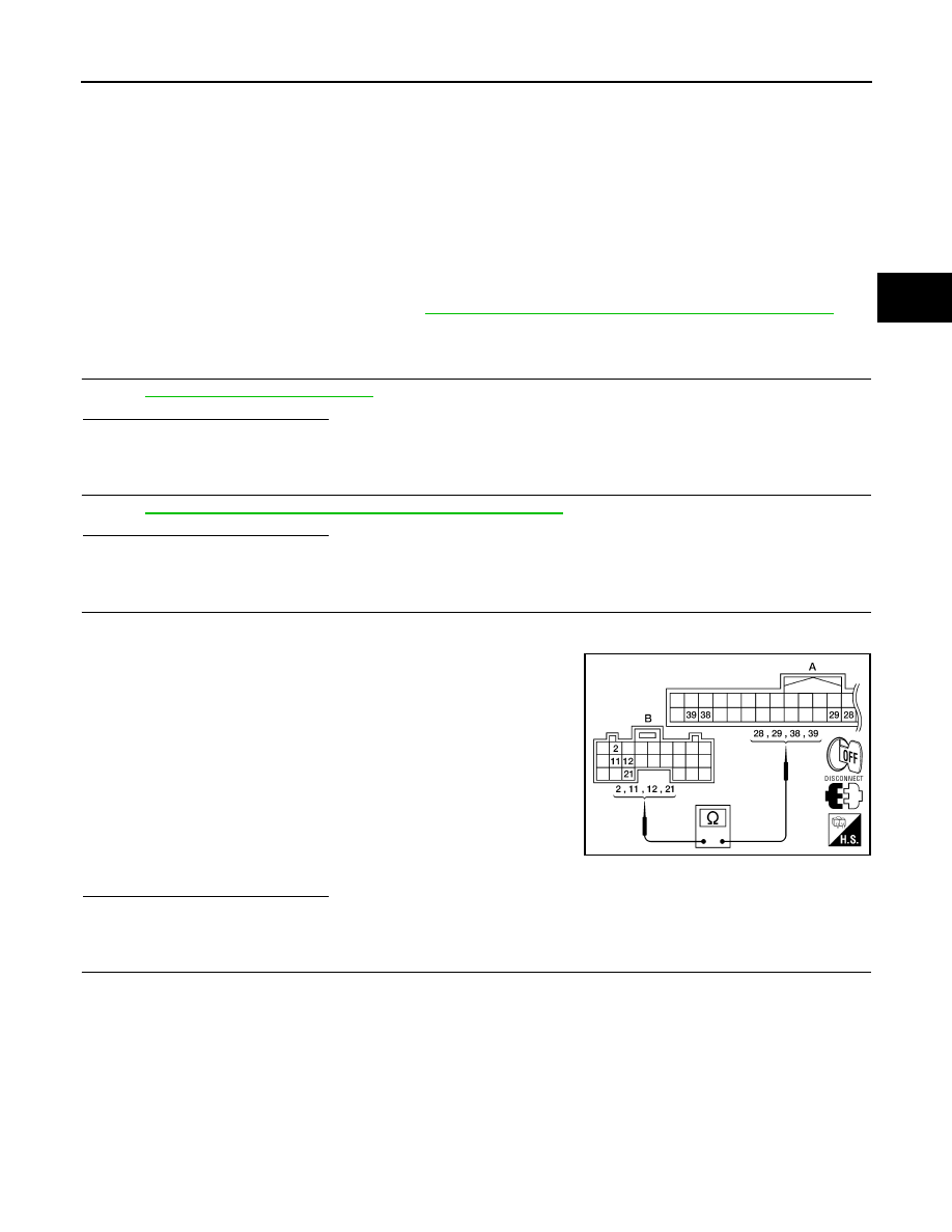
CHECK HARNESS BETWEEN TRANSFER CONTROL UNIT AND COMBINATION METER
1. Turn ignition switch OFF. (Stay for at least 5 seconds.)
2. Disconnect transfer control unit harness connector.
3. Check continuity between the following terminals.
-
Transfer control unit harness connector E142 (B) terminal 2 and
combination meter harness connector M24 (A) terminal 38.
-
Transfer control unit harness connector E142 (B) terminal 11
and combination meter harness connector M24 (A) terminal 29.
-
Transfer control unit harness connector E142 (B) terminal 12
and combination meter harness connector M24 (A) terminal 39.
-
Transfer control unit harness connector E142 (B) terminal 21
and combination meter harness connector M24 (A) terminal 28.
Also check harness for short to ground and short to power.
Are the inspection results normal?
YES
>> GO TO 4.
NO
>> Repair or replace damaged parts.
4.
CHECK INDICATOR LAMP CIRCUIT
1. Connect combination meter harness connector.
2. Turn ignition switch ON.
Continuity should exist.
AWDIA0184ZZ