Infiniti QX56 (JA60). Manual - part 232
STEERING LOCK UNIT
DLK-99
< COMPONENT DIAGNOSIS >
[WITH INTELLIGENT KEY SYSTEM]
C
D
E
F
G
H
I
J
L
M
A
B
DLK
N
O
P
STEERING LOCK UNIT
Diagnosis Procedure
INFOID:0000000005146970
Regarding Wiring Diagram information, refer to
DLK-178, "Wiring Diagram — INTELLIGENT KEY SYSTEM —
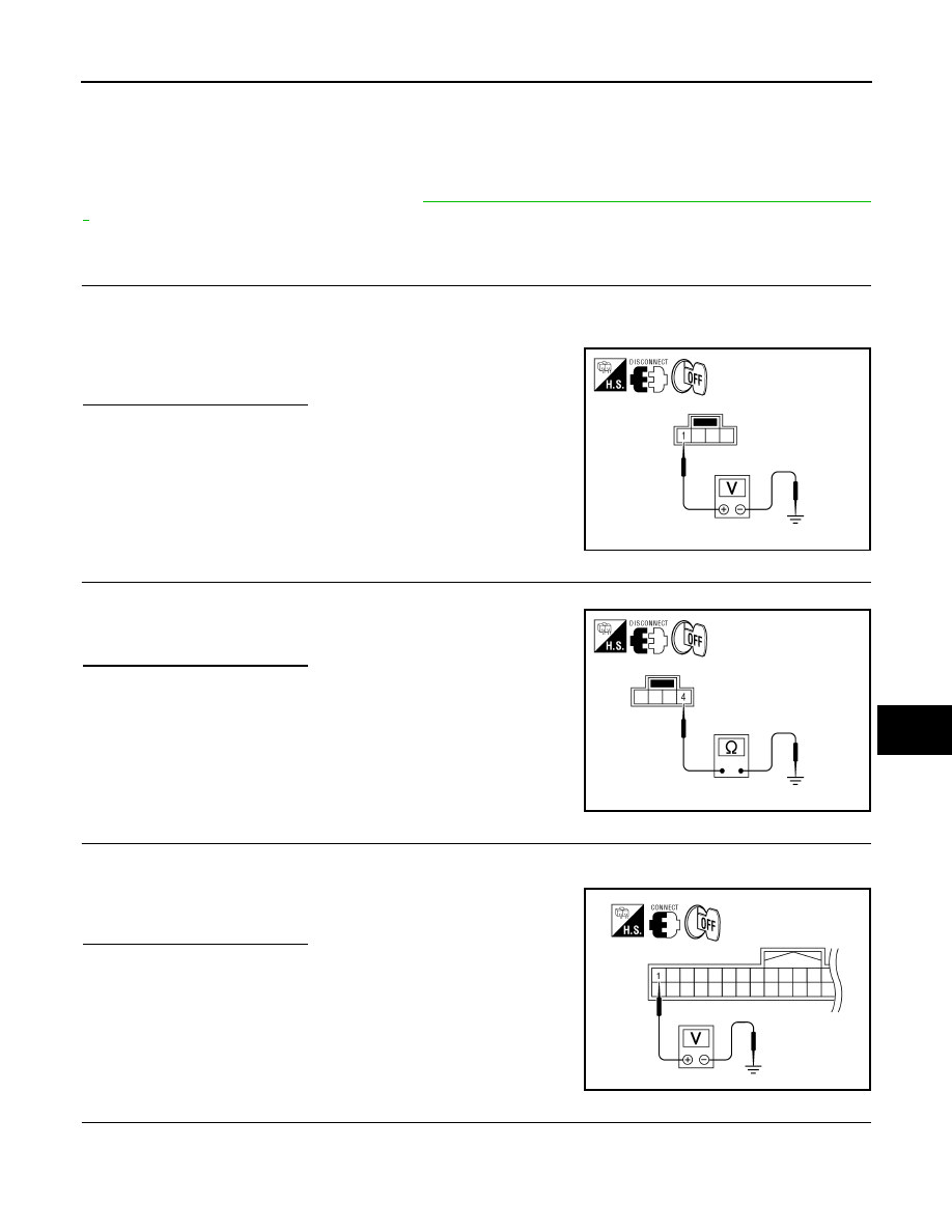
1.
CHECK STEERING LOCK SOLENOID POWER SUPPLY
1. Turn ignition switch OFF.
2. Disconnect steering lock solenoid connector.
3. Check voltage between steering lock solenoid harness connector M15 terminal 1 and ground.
Is the inspection result normal?
YES
>> GO TO 2
NO
>> Repair or replace steering lock solenoid power supply
circuit.
2.
CHECK STEERING LOCK SOLENOID GROUND CIRCUIT
Check continuity between steering lock solenoid harness connector M15 terminal 4 and ground.
Is the inspection result normal?
YES
>> GO TO 3
NO
>> Repair or replace the steering lock solenoid ground cir-
cuit.
3.
CHECK INTELLIGENT KEY UNIT OUTPUT SIGNAL
1. Connect steering lock solenoid connector.
2. Check voltage between Intelligent Key unit harness connector M70 terminal 1 and ground.
Is the inspection result normal?
YES
>> GO TO 4
NO
>> GO TO 6
4.
CHECK STEERING LOCK COMMUNICATION SIGNAL
Check signal between Intelligent Key unit connector M70 terminal 32 and ground with oscilloscope.
1 - Ground
: Battery voltage
WIIA1202E
4 - Ground
: Continuity should exist.
WIIA1203E
1 - Ground
: Approx. 5V
WIIA1204E