Infiniti QX56 (JA60). Manual - part 140
C1178, C1181, C1184, C1189 ABS ACTIVE BOOSTER
BRC-73
< COMPONENT DIAGNOSIS >
[VDC/TCS/ABS]
C
D
E
G
H
I
J
K
L
M
A
B
BRC
N
O
P
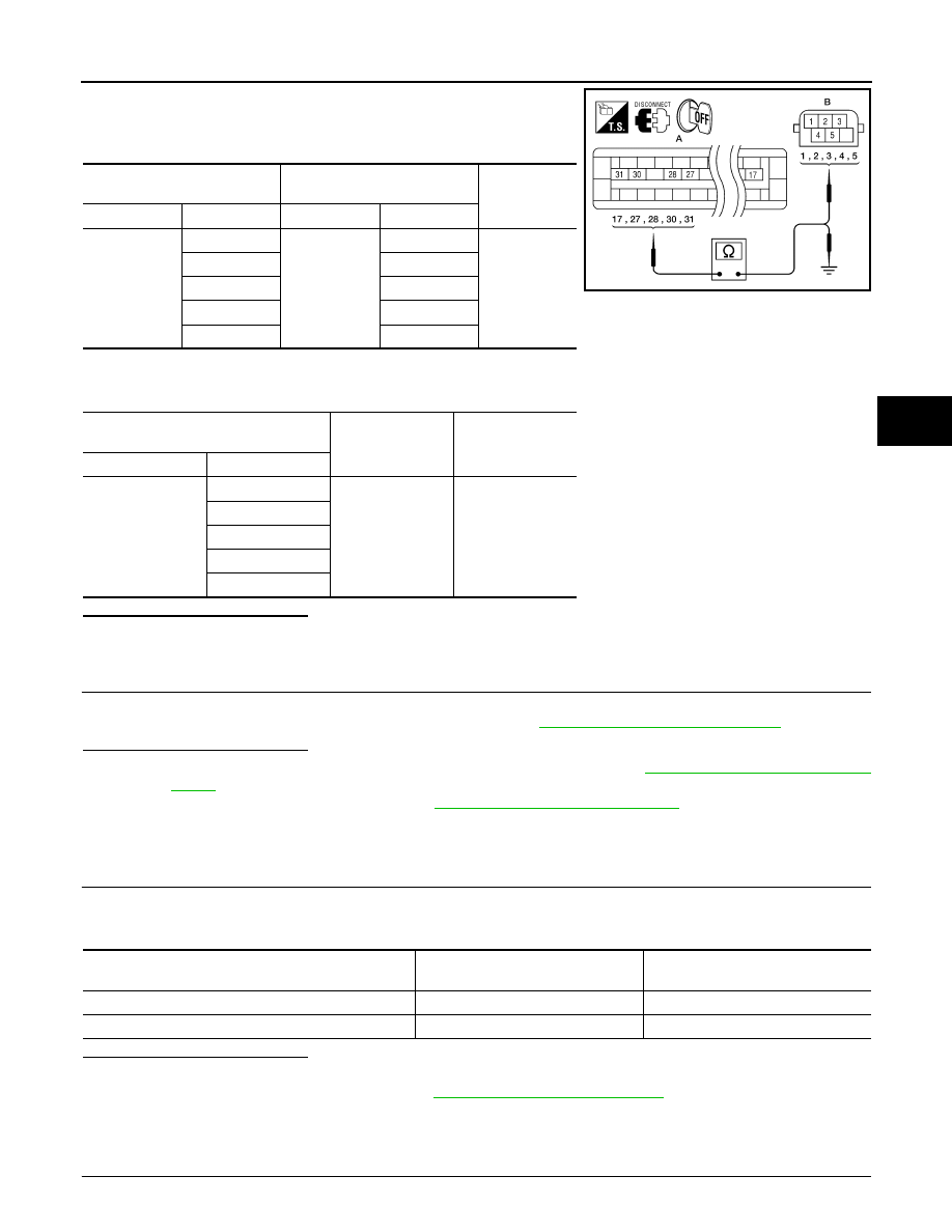
1. Measure the continuity between ABS actuator and electric unit
(control unit) connector E125 (A) and active booster connector
E49 (B).
2. Measure the continuity between ABS actuator and electric unit (control unit) connector E125 (A) and body
ground.
Is the inspection result normal?
YES
>> GO TO 3
NO
>> Repair or replace harness or connector.
3.
ACTIVE BOOSTER INSPECTION
1. Reconnect the active booster and ABS actuator and electric unit (control unit) connectors.
2. Perform the active booster component inspection. Refer to
BRC-73, "Component Inspection"
Is the inspection result normal?
YES
>> Replace the ABS actuator and electric unit (control unit). Refer to
.
NO
>> Replace the active booster. Refer to
BR-26, "Removal and Installation"
.
Component Inspection
INFOID:0000000005148050
1.
CHECK DATA MONITOR
Use “DATA MONITOR” to check if the status of “RELEASE SWITCH NO” and “RELEASE SWITCH NC” is nor-
mal.
Is the inspection result normal?
YES
>> Inspection End
NO
>> Go to diagnosis procedure. Refer to
Special Repair Requirement
INFOID:0000000005194921
1.
ADJUSTMENT OF STEERING ANGLE SENSOR NEUTRAL POSITION
ABS actuator and electric unit
(control unit)
Active booster
Continuity
Connector
Terminal
Connector
Terminal
E125 (A)
17
E49 (B)
3
Yes
27
1
28
5
30
2
31
4
ABS actuator and electric unit (control
unit)
—
Continuity
Connector
Terminal
E125 (A)
17
Ground
No
27
28
30
31
AWFIA0028ZZ
Condition
RELEASE SWITCH NO
(DATA MONITOR)
RELEASE SWITCH NC
(DATA MONITOR)
When brake pedal is applied.
ON
OFF
When brake pedal is released.
OFF
ON