Infiniti QX56 (Z62). Manual - part 831
INL-54
< BASIC INSPECTION >
DIAGNOSIS AND REPAIR WORKFLOW
BASIC INSPECTION
DIAGNOSIS AND REPAIR WORKFLOW
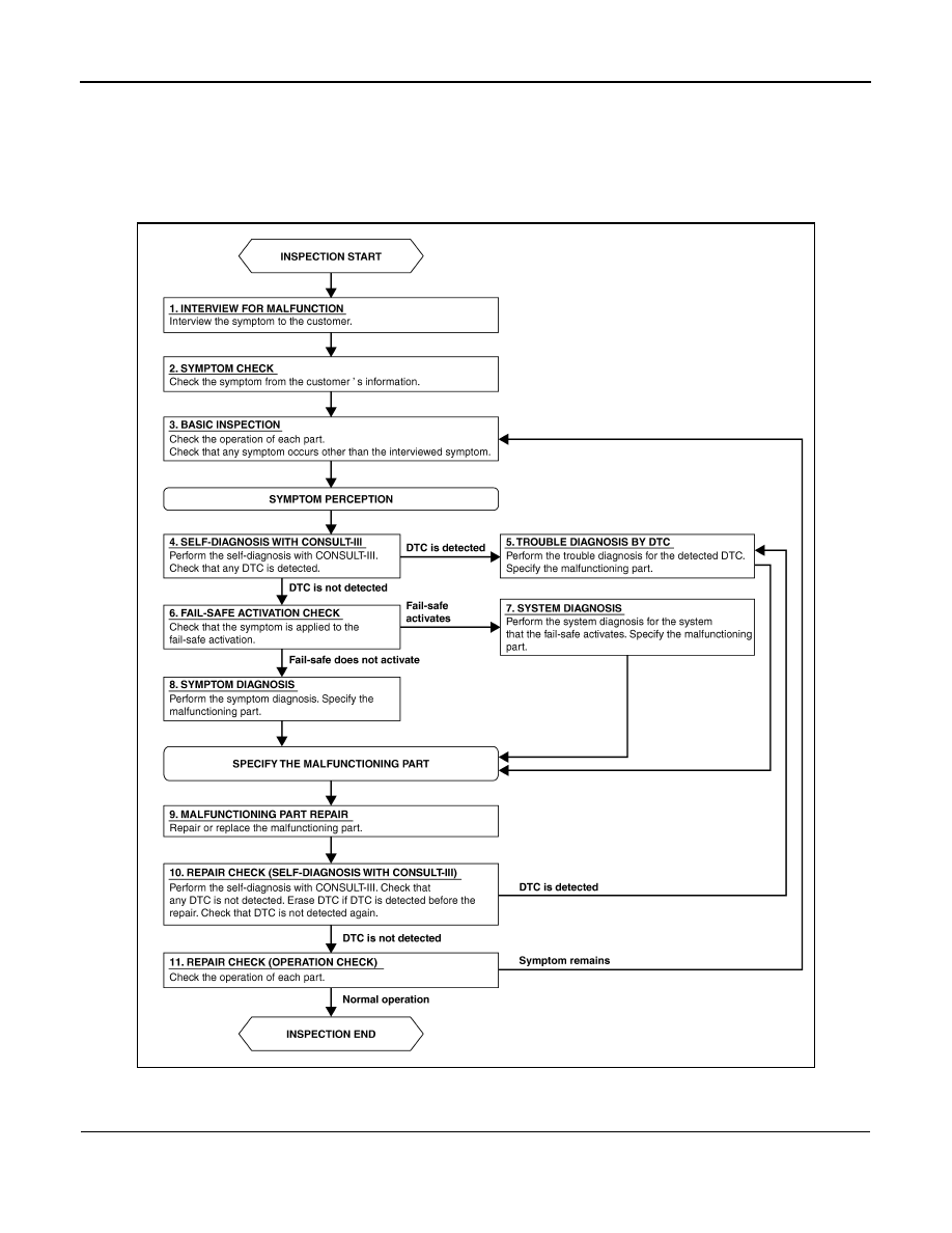
Work Flow
INFOID:0000000006216064
OVERALL SEQUENCE
DETAILED FLOW
1.
INTERVIEW FOR MALFUNCTION
Interview the symptom to the customer.
JPLIA0313GB