Infiniti QX56 (Z62). Manual - part 787


  Index      Infiniti     Infiniti QX56 (Z62) - service repair manual 2011 year


Search            


Content   ..  785  786  787  788   ..


Infiniti QX56 (Z62). Manual - part 787


DIAGNOSIS SYSTEM (HVAC)

HAC-39

< SYSTEM DESCRIPTION >

[AUTOMATIC AIR CONDITIONING]

C

D

E

F

G

H

J

K

L

M

A

B

HAC

N

O

P

DIAGNOSIS SYSTEM (HVAC)

Description

INFOID:0000000006275884

Air conditioning system performs self-diagnosis, operation check, function diagnosis, and various settings
using diagnosis function of each control unit.

CONSULT-III Function

INFOID:0000000006275885

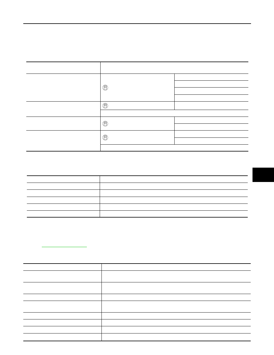
CONSULT-III performs the following functions via CAN communication with A/C auto amp. 

NOTE:
Diagnosis should be performed with engine running. Door motor operation speeds become slower and NO
results may be returned even for normal operation if battery voltage drops below 12 V during self-diagnosis. 

SELF-DIAGNOSIS RESULTS

Refer to 

HAC-45, "DTC Index"

.

DATA MONITOR

Display item list

ECU

Diagnostic item

(CONSULT-III)

A/C auto amp.

HVAC

Self Diagnostic Result

Data Monitor

Active Test

Work support

AV control unit

MULTI AV

Self Diagnostic Result

Multi AV system on board diagnosis function

ECM

ENGINE

Self Diagnostic Result

Data Monitor

IPDM E/R

IPDM E/R

Self Diagnostic Result

Data Monitor

Auto active test

Diagnostic mode

Description

Self diagnostic result

Displays the diagnosis results judged by A/C auto amp. 

Data monitor

Displays the input/output signal of A/C auto amp. 

Active test

The signals used to activate each device are forcibly supplied from A/C auto amp. 

Work support

Changes the setting for each setting function. 

ECU identification

Displays the part number of A/C auto amp. 

Monitor item [Unit]

Description

AMB TEMP SEN

[

°

C (

°

F)]

Ambient sensor value converted from ambient sensor signal received from ambient sen-
sor 

IN-VEH TEMP

[

°

C (

°

F)]

Front in-vehicle sensor value converted from front in-vehicle sensor signal received from 
front in-vehicle sensor

INT TEMP SEN

[

°

C (

°

F)]

Intake sensor value converted from intake sensor signal received from intake sensor 

SUNLOAD SEN

[w/m

2

]

Sunload sensor value converted from sunload sensor signal (driver side) received from 
sunload sensor 

AMB SEN CAL

[

°

C (

°

F)]

Ambient temperature value calculated by A/C auto amp.

IN-VEH CAL

[

°

C (

°

F)]

In-vehicle temperature (front side) value calculated by A/C auto amp.

INT TEMP CAL

[

°

C (

°

F)]

Front evaporator fin temperature value calculated by A/C auto amp.

SUNL SEN CAL

[w/m

2

]

Sunload value (driver side) calculated by A/C auto amp.

HAC-40

< SYSTEM DESCRIPTION >

[AUTOMATIC AIR CONDITIONING]

DIAGNOSIS SYSTEM (HVAC)

ACTIVE TEST

Check each output device

COMP REQ SIG

[On/Off]

Displays A/C switch ON/OFF status transmitted to other units via CAN communication

FAN REQ SIG

[On/Off]

Displays front blower motor ON/OFF status transmitted to other units via CAN commu-
nication

FAN DUTY

Duty ratio of front blower motor judged by A/C auto amp.

XM

Target discharge front air temperature (driver side) judged by A/C auto amp. depending 
on the temperature setting and the value from each sensor

PASS SUNL CAL

[w/m

2

]

Sunload value (passenger side) calculated by A/C auto amp.

PASS SUNLOAD SEN

[w/m

2

]

Sunload sensor value converted from sunload sensor signal (passenger side) received 
from sunload sensor 

PA TARGET A/TEMP

Target discharge front air temperature (passenger side) judged by A/C auto amp. de-
pending on the temperature setting and the value from each sensor

RRIN TEMP SEN

[

°

C (

°

F)]

Rear in-vehicle sensor value converted from rear in-vehicle sensor signal received from 
rear in-vehicle sensor.

RRIN TEMP CAL

[

°

C (

°

F)]

In-vehicle temperature (rear side) value calculated by A/C auto amp.

RR INT TMP CL

[

°

C (

°

F)]

Rear evaporator fin temperature value calculated by A/C auto amp.

RRFAN REQ SIG

[On/Off]

Displays rear blower motor ON/OFF status transmitted to other units via CAN communi-
cation

RR FAN DUTY

Duty ratio of rear blower motor judged by A/C auto amp.

RR XM

Target discharge rear air temperature (driver side) judged by A/C auto amp. depending 
on the temperature setting and the value from each sensor

ENG COOL TEMP

[

°

C (

°

F)]

Engine coolant temperature signal value received from ECM via CAN communication

VEHICLE SPEED

[km/h

(mph)]

Vehicle speed signal value received from combination meter via CAN communication

Monitor item [Unit]

Description

Test item

Description

HVAC TEST

The operation check of air conditioning system can be performed by selecting the mode. 
Refer to the following table for the conditions of each mode. 

Test item

MODE 1

MODE 2

MODE 3

MODE 4

MODE 5

MODE 6

MODE 7

Front mode door motor posi-
tion

VENT

VENT

B/L

B/L

FOOT

D/F

DEF

Intake door motor position

REC

REC

20% FRE

20% FRE

FRE

FRE

FRE

Front air mix door motor (driver 
side) position

FULL COLD

FULL COLD

FULL COLD

FULL HOT

FULL HOT

FULL HOT

FULL HOT

Front air mix door motor (pas-
senger side) position

FULL COLD

FULL COLD

FULL COLD

FULL HOT

FULL HOT

FULL HOT

FULL HOT

Front blower motor control sig-
nal duty ratio

35%

35%

59%

59%

89%

89%

35%

Magnet clutch

ON

ON

ON

ON

OFF

OFF

ON

Upper ventilator door motor 
position

OPEN

CLOSE

OPEN

CLOSE

CLOSE

CLOSE

CLOSE

Rear mode door motor posi-
tion

VENT

VENT

B/L

B/L

FOOT

FOOT

FOOT

Rear air mix door motor posi-
tion

FULL COLD

FULL COLD

FULL COLD

FULL HOT

FULL HOT

FULL HOT

FULL HOT

Rear blower motor control sig-
nal duty ratio

35%

35%

59%

59%

89%

89%

35%

DIAGNOSIS SYSTEM (HVAC)

HAC-41

< SYSTEM DESCRIPTION >

[AUTOMATIC AIR CONDITIONING]

C

D

E

F

G

H

J

K

L

M

A

B

HAC

N

O

P

*: With ACCS (advanced climate control system)
NOTE:
Perform the inspection of each output device after starting the engine because the compressor is operated. 

WORK SUPPORT

*: With ACCS (advanced climate control system)
NOTE:
When the battery cable is disconnected from the negative terminal or when the battery voltage becomes 10 V
or less, the setting of WORK SUPPORT may be cancelled. 

Rear A/C relay

ON

ON

ON

ON

OFF

OFF

ON

Ionizer

*

ON

ON

ON

ON

ON

ON

OFF

Front display (Ion mode)

*

CLEAN

CLEAN

QUICK 

CLEAN

QUICK 

CLEAN

QUICK 

CLEAN

QUICK 

CLEAN

OFF

Test item

MODE 1

MODE 2

MODE 3

MODE 4

MODE 5

MODE 6

MODE 7

Work item

Description

Refer to

TEMP SET CORRECT

Setting change of temperature setting trimmer (front) can be per-
formed. 

HAC-68, "FRONT AUTO-
MATIC AIR CONDITION-
ING SYSTEM : 
Temperature Setting Trim-
mer (Front)"

BLOWER SET

Setting change of foot position setting trimmer can be performed. 

HAC-68, "FRONT AUTO-
MATIC AIR CONDITION-
ING SYSTEM : Foot 
Position Setting Trimmer"

REC MEMORY SET

Setting change of inlet port memory function (REC) can be per-
formed. 

HAC-69, "FRONT AUTO-
MATIC AIR CONDITION-
ING SYSTEM : Inlet Port 
Memory Function (REC)"

FRE MEMORY SET

Setting change of inlet port memory function (FRE) can be per-
formed. 

HAC-69, "FRONT AUTO-
MATIC AIR CONDITION-
ING SYSTEM : Inlet Port 
Memory Function (FRE)"

GAS SENSOR ADJUSTMENT

*

Setting change of exhaust gas / outside odor detecting sensor sensi-
tivity adjustment function can be performed. 

HAC-70, "ACCS (AD-
VANCED CLIMATE CON-
TROL SYSTEM) : 
Exhaust Gas / Outside 
Odor Detecting Sensor 
Sensitivity Adjustment 
Function"

CLEAN SW SET

*

Setting change of auto intake switch interlocking movement change 
function can be performed. 

HAC-70, "ACCS (AD-
VANCED CLIMATE CON-
TROL SYSTEM) : Auto 
Intake Switch Interlocking 
Movement Change Func-
tion"

REAR TEMP SET CORRECT

Setting change of temperature setting trimmer (rear) can be per-
formed. 

HAC-68, "FRONT AUTO-
MATIC AIR CONDITION-
ING SYSTEM : 
Temperature Setting Trim-
mer (Front)"

HAC-42

< ECU DIAGNOSIS INFORMATION >

[AUTOMATIC AIR CONDITIONING]

A/C AUTO AMP.

ECU DIAGNOSIS INFORMATION

A/C AUTO AMP.

Reference Value

INFOID:0000000006275886

CONSULT-III DATA MONITOR REFERENCE VALUES

Monitor item

Condition

Value/Status

AMB TEMP SEN

Ignition switch ON

Equivalent to ambient tem-
perature

IN-VEH TEMP

Ignition switch ON

Equivalent to in-vehicle tem-
perature (front side)

INT TEMP SEN

Ignition switch ON

Equivalent to front evapora-
tor fin temperature

SUNLOAD SEN

Ignition switch ON

Equivalent to sunload (driver 
side)

AMB SEN CAL

Ignition switch ON

Equivalent to ambient tem-
perature

IN-VEH CAL

Ignition switch ON

Equivalent to in-vehicle tem-
perature (front side)

INT TEMP CAL

Ignition switch ON

Equivalent to front evapora-
tor fin temperature

SUNL SEN CAL

Ignition switch ON

Equivalent to sunload (driver 
side)

COMP REQ SIG

Engine: Run at idle after 
warming up 

A/C switch: ON
(Compressor operation sta-
tus) 

On

A/C switch: OFF

Off

FAN REQ SIG

Engine: Run at idle after 
warming up 

Front blower motor: ON

On

Front blower motor: OFF

Off

FAN DUTY

Engine: Run at idle after 
warming up 

Front blower motor: ON

25 – 81

Front blower motor: OFF

0

XM

Ignition switch ON

Value according to target air 
flow temperature (driver 
side)

PASS SUNL CAL

Ignition switch ON

Equivalent to sunload (pas-
senger side)

PASS SUNLOAD SEN

Ignition switch ON

Equivalent to sunload (pas-
senger side)

PA TARGET A/TEMP

Ignition switch ON

Value according to target air 
flow temperature (passen-
ger side)

RRIN TEMP SEN

Ignition switch ON

Equivalent to in-vehicle tem-
perature (rear side)

RRIN TEMP CAL

Ignition switch ON

Equivalent to in-vehicle tem-
perature (rear side)

RR INT TMP CL

Ignition switch ON

Equivalent to rear evapora-
tor fin temperature

RRFAN REQ SIG

Engine: Run at idle after 
warming up 

Rear blower motor: ON

On

Rear blower motor: OFF

Off

RR FAN DUTY

Engine: Run at idle after 
warming up 

Rear blower motor: ON

25 – 81

Rear blower motor: OFF

0


Content   ..  785  786  787  788   ..