Infiniti QX56 (Z62). Manual - part 623
EC-470
< DTC/CIRCUIT DIAGNOSIS >
[VK56VD]
P2122, P2123 APP SENSOR
Replace accelerator pedal assembly. Refer to
ACC-3, "MODELS WITHOUT DISTANCE CONTROL ASSIST
SYSTEM : Removal and Installation"
(Without distance control assist system) or
DISTANCE CONTROL ASSIST SYSTEM : Removal and Installation"
(With distance control assist system).
>> INSPECTION END
9.
CHECK INTERMITTENT INCIDENT
GI-40, "Intermittent Incident"
>> INSPECTION END
Component Inspection (Accelerator Pedal Position Sensor)
INFOID:0000000006217974
1.
CHECK ACCELERATOR PEDAL POSITION SENSOR
1.
Turn ignition switch OFF.
2.
Reconnect all harness connectors disconnected.
3.
Turn ignition switch ON.
4.
Check the voltage ECM harness connector terminals under the following conditions.
Is the inspection result normal?
YES
>> INSPECTION END
NO
>> GO TO 2.
2.
REPLACE ACCELERATOR PEDAL ASSEMBLY
Replace accelerator pedal assembly. Refer to
ACC-3, "MODELS WITHOUT DISTANCE CONTROL ASSIST
SYSTEM : Removal and Installation"
(Without distance control assist system) or
DISTANCE CONTROL ASSIST SYSTEM : Removal and Installation"
(With distance control assist system).
>> INSPECTION END
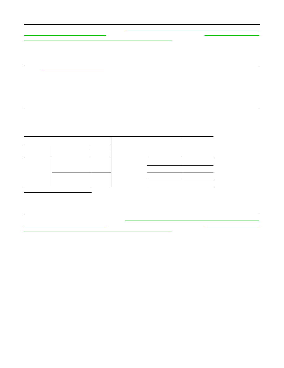
ECM
Condition
Voltage (V)
Connector
+
–
Terminal
Terminal
E80
136 (APP sensor 1)
140
Accelerator pedal
Fully released
0.65 - 0.87
Fully depressed
4.3 - 4.8
126 (APP sensor 2)
129
Fully released
0.28 - 0.48
Fully depressed
2.0 - 2.5