Infiniti QX56 (Z62). Manual - part 575
EC-278
< DTC/CIRCUIT DIAGNOSIS >
[VK56VD]
P0190, P0192, P0193 FRP SENSOR
6.
CHECK FRP SENSOR SIGNAL CIRCUIT
1.
Turn ignition switch OFF.
2.
Disconnect ECM harness connector.
3.
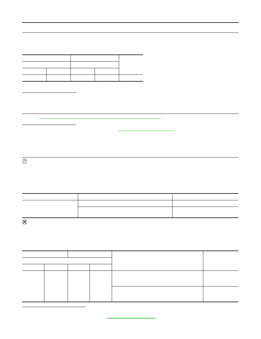
Check the continuity between FRP sensor harness connector and ECM harness connector.
4.
Also check harness for short to ground and to power.
Is inspection result normal?
YES
>> GO TO 7.
NO
>> Repair or replace error-detected parts.
7.
CHECK FRP SENSOR
EC-278, "Component Inspection (Fuel Rail Pressure Sensor)"
Is inspection result normal?
YES
>> Check intermittent incident. Refer to
GI-40, "Intermittent Incident"
.
NO
>> Repair or replace error-detected parts.
Component Inspection (Fuel Rail Pressure Sensor)
INFOID:0000000006288297
1.
CHECK FRP SENSOR
WITH CONSULT-III
1.
Turn ignition switch OFF.
2.
Reconnect harness connector disconnected.
3.
Start the engine.
4.
Select “DATA MONITOR” mode with CONSULT-III.
5.
Check that the “FUEL PRES SEN V” indication.
WITHOUT CONSULT-III
1.
Turn ignition switch OFF.
2.
Reconnect harness connector disconnected.
3.
Start the engine.
4.
Check FRP sensor signal voltage.
Is the inspection result normal?
YES
>> INSPECTION END.
NO
>> Replace FRP sensor. Refer to
+
−
Continuity
FRP sensor
ECM
Connector
Terminal
Connector
Terminal
F26
2
F111
31
Existed
Monitor Item
Condition
Values/Status
FUEL PRES SEN V
Engine speed: Idle
980 – 1,200 mV
Engine speed: Revving engine from idle to 4,000 rpm
quickly
1,100 – 2,900 mV
+
−
Condition
Value
(Approx.)
ECM
Connector
Terminal
Connector
Terminal
F111
31
F111
40
[Engine is running]
• Warm-up condition
• Idle speed
0.98 – 1.2 V
[Engine is running]
• Warm-up condition
• Revving engine from idle to 4,000 rpm quickly
1.1 – 2.9 V