Infiniti QX56 (Z62). Manual - part 134


  Index      Infiniti     Infiniti QX56 (Z62) - service repair manual 2011 year


Search            


Content   ..  132  133  134  135   ..


Infiniti QX56 (Z62). Manual - part 134


SYSTEM

BRC-21

< SYSTEM DESCRIPTION >

[WITH VDC]

C

D

E

G

H

I

J

K

L

M

A

B

BRC

N

O

P

• Being returned to reservoir tank through ABS OUT valve, fluid pressure of rear LH caliper is decreased.

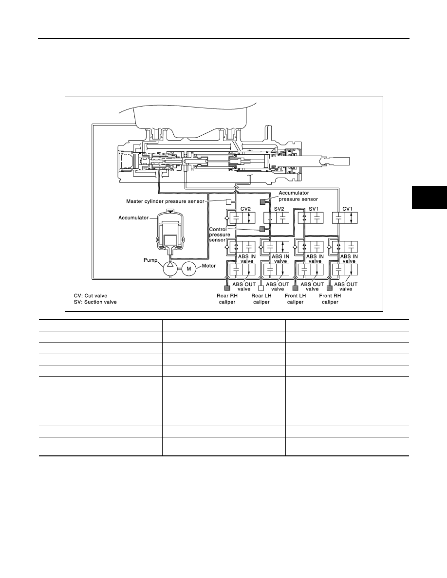
VDC is Operation (When Pressure Increases)

NOTE:
Control pressure sensor is applied to models with Advanced Driver Assistance System.
Example: When other than rear LH wheel is operation in the figure.

Front RH caliper

• Pressurized brake fluid from accumulator is supplied to front RH caliper through suction valve 2, suction

valve 1 and ABS IN valve. When not increases, ABS IN valve is closed and brakes fluid is not supplied to
front RH caliper.

Front LH caliper

• Pressurized brake fluid from accumulator is supplied to front LH caliper through suction valve 2, suction

valve 1 and ABS IN valve. When not increases, ABS IN valve is closed and brakes fluid is not supplied to
front LH caliper.

Rear RH caliper

Name

Not activated

When Pressure Increases

Cut valve 1

Power supply is not supplied (open)

Power supply is supplied (close)

Cut valve 2

Power supply is not supplied (open)

Power supply is supplied (close)

Suction valve 1

Power supply is not supplied (close)

Power supply is supplied (open)

Suction valve 2

Power supply is not supplied (close)

Power supply is supplied (open)

ABS IN valve

Power supply is not supplied (open)

Only wheel that the pressure is to be in-

creased: Power supply is not supplied 

(open)

Wheel other than the one that the pressure 
is to be increased: Power supply is supplied 

(close)

ABS OUT valve

Power supply is not supplied (close)

Power supply is not supplied (close)

Each caliper (fluid pressure)

Pressure increases (only wheel that the 

pressure is to be increased)

JPFIC0154GB

BRC-22

< SYSTEM DESCRIPTION >

[WITH VDC]

SYSTEM

• Pressurized brake fluid from accumulator is supplied to rear RH caliper through suction valve 2 and ABS IN

valve. When not increases, ABS IN valve is closed and brakes fluid is not supplied to rear RH caliper.

Rear LH caliper

• Pressurized brake fluid from accumulator is supplied to rear LH caliper through suction valve 2 and ABS IN

valve. When not increases, ABS IN valve is closed and brakes fluid is not supplied to rear LH caliper.

VDC is Operation (When Pressure Holds)

NOTE:
Control pressure sensor is applied to models with Advanced Driver Assistance System.
Example: When other than front LH wheel is operation in the figure.

Front RH caliper

• ABS IN valve is close, fluid pressure of front RH caliper is holds.

Front LH caliper

• ABS IN valve is close, fluid pressure of front LH caliper is holds.

Rear RH caliper

• ABS IN valve is close, fluid pressure of rear RH caliper is holds.

Name

Not activated

When Pressure holds

Cut valve 1

Power supply is not supplied (open)

Power supply is supplied (close)

Cut valve 2

Power supply is not supplied (open)

Power supply is supplied (close)

Suction valve 1

Power supply is not supplied (close)

Power supply is supplied (open)

Suction valve 2

Power supply is not supplied (close)

Power supply is supplied (open)

ABS IN valve

Power supply is not supplied (open)

Only wheel that the pressure is to be holds: 

Power supply is supplied (close)

Wheel other than the one that the pressure 
is to be holds: Power supply is not supplied 

(open)

ABS OUT valve

Power supply is not supplied (close)

Power supply is not supplied (close)

Each caliper (fluid pressure)

Pressure holds (only wheel that the pres-

sure is to be holds)

JPFIC0180GB

SYSTEM

BRC-23

< SYSTEM DESCRIPTION >

[WITH VDC]

C

D

E

G

H

I

J

K

L

M

A

B

BRC

N

O

P

Rear LH caliper

• ABS IN valve is close, fluid pressure of rear LH caliper is holds.

VDC is Operation (When Pressure Decreases)

NOTE:
Control pressure sensor is applied to models with Advanced Driver Assistance System.
Example: When other than front LH wheel is operation in the figure.

Front RH caliper

• Being returned to reservoir tank through ABS OUT valve, fluid pressure of front RH caliper is decreased.

Front LH caliper

• Being returned to reservoir tank through ABS OUT valve, fluid pressure of front LH caliper is decreased.

Rear RH caliper

• Being returned to reservoir tank through ABS OUT valve, fluid pressure of rear RH caliper is decreased.

Name

Not activated

When pressure decreases

Cut valve 1

Power supply is not supplied (open)

Power supply is supplied (close)

Cut valve 2

Power supply is not supplied (open)

Power supply is supplied (close)

Suction valve 1

Power supply is not supplied (close)

Power supply is supplied (open)

Suction valve 2

Power supply is not supplied (close)

Power supply is supplied (open)

ABS IN valve

Power supply is not supplied (open)

Only wheel that the pressure is to be de-

creases: Power supply is supplied (close)

Wheel other than the one that the pressure 

is to be decreases: Power supply is not 

supplied (open)

ABS OUT valve

Power supply is not supplied (close)

Only wheel that the pressure is to be de-

creases: Power supply is supplied (open)

Wheel other than the one that the pressure 

is to be decreases: Power supply is not 

supplied (close)

Each caliper (fluid pressure)

Pressure decreases (only wheel that the 

pressure is to be decreases)

JPFIC0181GB

BRC-24

< SYSTEM DESCRIPTION >

[WITH VDC]

SYSTEM

Rear LH caliper

• Being returned to reservoir tank through ABS OUT valve, fluid pressure of rear LH caliper is decreased.

Component Parts and Function

*: Models with Advanced Driver Assistance System

CONDITION FOR TURN ON THE WARNING LAMP

ABS Warning Lamp

• Turns ON at the same time as VDC warning lamp when either ABS function or EBD function is malfunction-

ing.

• Turns ON when ignition switch turns ON and turns OFF when the system is normal, for bulb check purposes.

Brake Warning Lamp

• Turns ON at the same time as ABS warning lamp and VDC warning lamp when EBD function, motor/accu-

mulator assembly or motor system is malfunctioning.

• Turns ON when ignition switch turns ON and turns OFF when the system is normal, for bulb check purposes.

Component

Function

Pump

Operates the pump drive according to signals from ABS actuator and electric unit (control unit) by 
the motor.

Motor

Operates the motor drive according to signals from ABS actuator and electric unit (control unit).

Accumulator

The accumulator accumulates brake fluid conveyed by the motor and pump.

ABS IN valve

Increases, holds or decreases the fluid pressure of each caliper according to signals from ABS ac-
tuator and electric unit (control unit).

ABS OUT valve

Increases, holds or decreases the fluid pressure of each caliper according to signals from ABS ac-
tuator and electric unit (control unit).

Cut valve 1
Cut valve 2

Shuts off the ordinary brake line from master cylinder to signals from ABS actuator and electric unit 
(control unit).

Suction valve 1

Suction Valve 1 switches the brake line to convey accumulator pressure to the front system, accord-
ing to a signal transmitted from the ABS actuator and electric unit (control unit).

Suction valve 2

Suction valve 2 releases accumulator pressure, according to a signal transmitted from the ABS ac-
tuator and electric unit (control unit).

Control pressure sensor

*

Detects the brake fluid pressure of rear brake caliper and transmits a signal to ABS actuator and 
electric unit (control unit).

Accumulator pressure sensor

The accumulator pressure sensor detects brake fluid pressure accumulated in the accumulator and 
conveys the detected result to the ABS actuator and electric unit (control unit).

Master cylinder pressure sensor

Detects the brake fluid pressure of master cylinder part and transmits a signal to ABS actuator and 
electric unit (control unit).

Condition (status)

ABS warning lamp

Ignition switch OFF

OFF

For approx. 1 seconds after the ignition switch is turned ON

ON

Approx. 1 seconds after ignition switch is turned ON (when the 
system is in normal operation)

OFF

ABS function is malfunctioning

ON

EBD function is malfunctioning

ON

Condition (status)

Brake warning lamp

Ignition switch OFF

OFF

For approx. 1 seconds after the ignition switch is turned ON

ON

Approx. 1 seconds after ignition switch is turned ON (when the 
system is in normal operation)

OFF

After engine starts

OFF

When parking brake operates (parking brake switch ON)

ON


Content   ..  132  133  134  135   ..