Content .. 1067 1068 1069 1070 ..
Infiniti QX56 (Z62). Manual - part 1069
RSU-18
< UNIT REMOVAL AND INSTALLATION >
REAR SUSPENSION MEMBER
UNIT REMOVAL AND INSTALLATION
REAR SUSPENSION MEMBER
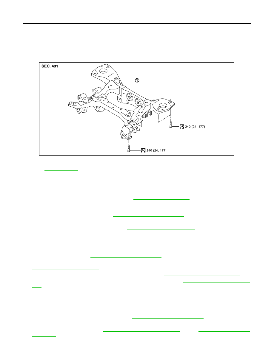
Exploded View
INFOID:0000000006225676
Removal and Installation
INFOID:0000000006225677
REMOVAL
1.
Reduce system pressure. (With HBMC) Refer to
.
CAUTION:
Inadvertent piping removal causes fluid to splatter.
2.
Remove tires with power tool. Refer to
WT-64, "Removal and Installation"
.
3.
Remove emergency tires.
4.
Remove front tube and main muffler. Refer to
EX-5, "Removal and Installation"
5.
Remove caliper assembly. Hang caliper assembly in a place where it will not interfere with work. Refer to
BR-43, "BRAKE CALIPER ASSEMBLY : Removal and Installation"
CAUTION:
Avoid depressing brake pedal while brake caliper is removed.
6.
Remove disc rotor. Refer to
RAX-7, "Removal and Installation"
.
7.
Remove wheel sensor harness from rear suspension member. Refer to
SOR : Removal and Installation"
.
8.
Remove height sensor from rear lower link (right side). Refer to
EXL-136, "Removal and Installation"
.
9.
Remove vehicle height sensor from rear lower link (left side). Refer to
SCS-98, "Removal and Installa-
10. Remove parking brake cable mounting bolt and separate parking brake cable from vehicle and rear sus-
pension member. Refer to
PB-5, "Removal and Installation"
.
11. Remove shock absorber mounting bolt (lower side).
12. Remove stabilizer bar. (Without HBMC). Refer to
RSU-17, "Removal and Installation"
.
13. Remove rear lower link and coil spring. Refer to
RSU-8, "Removal and Installation"
14. Remove drive shaft. Refer to
RAX-11, "Removal and Installation"
.
15. Remove propeller shaft. Refer to
DLN-137, "Removal and Installation"
(4WD).
1.
Rear suspension member
Refer to
for symbols in the figure.
JPEIB0218GB