Infiniti QX56 (Z62). Manual - part 85
AV-194
< DTC/CIRCUIT DIAGNOSIS >
STEERING SWITCH SIGNAL A CIRCUIT
Standard
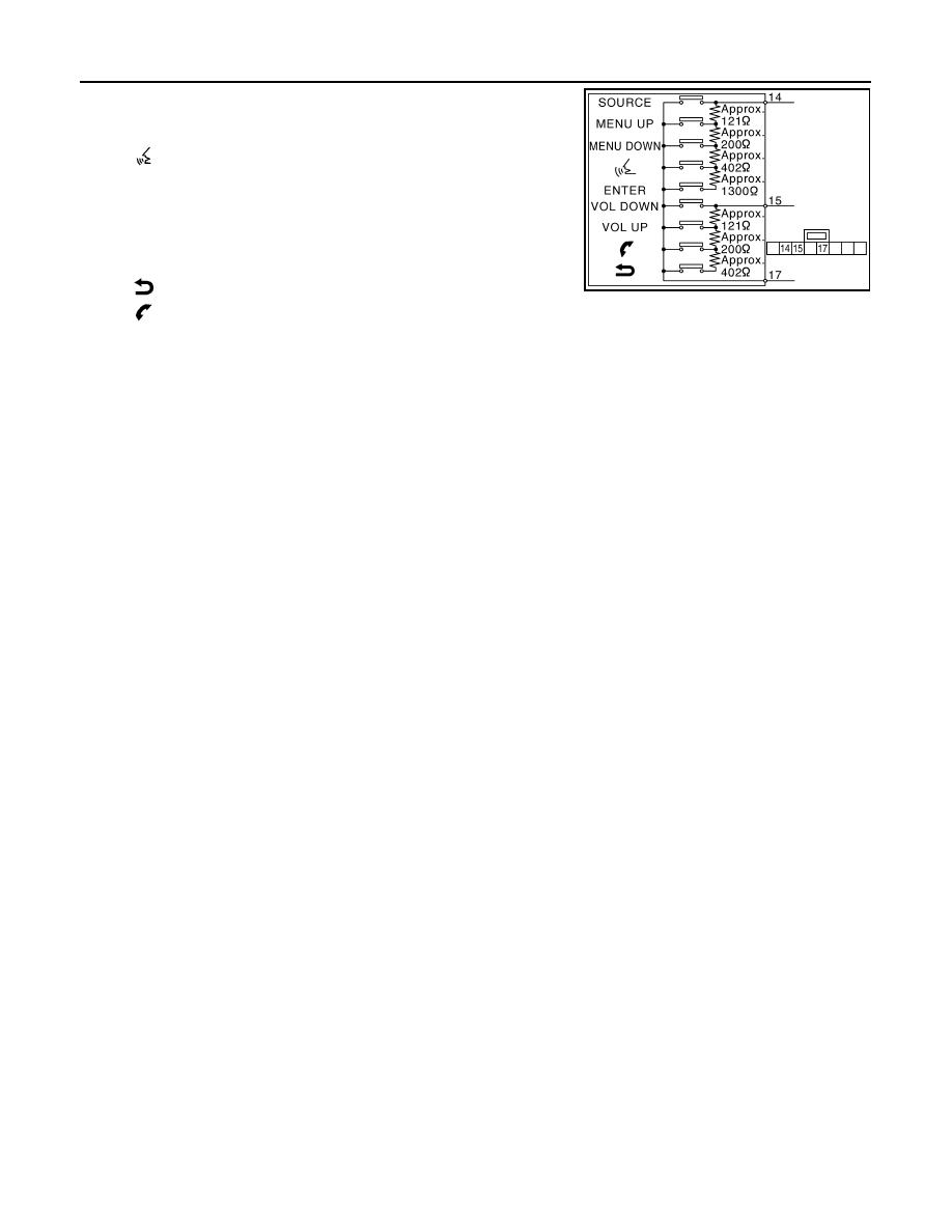
Between terminals 14 and 17
ENTER switch ON
: 2003 – 2043
Ω
switch ON
: 716 – 730
Ω
MENU DOWN switch ON
: 318 – 324
Ω
MENU UP switch ON
: 120 – 122
Ω
SOURCE switch ON
: 0
Ω
Between terminals 15 and 17
switch ON
: 716 – 730
Ω
switch ON
: 318 – 324
Ω
VOL UP switch ON
: 120 – 122
Ω
VOL DOWN switch ON
: 0
Ω
JSNIA0112GB