Infiniti QX56 (Z62). Manual - part 79
AV-170
< DTC/CIRCUIT DIAGNOSIS >
COMPOSITE IMAGE SIGNAL CIRCUIT (VIDEO DISTRIBUTOR TO HEADREST
DISPLAY UNIT)
*1: Headrest display unit LH
*2: Headrest display unit RH
Is the inspection result normal?
YES
>> Replace headrest display unit. Refer to
.
NO
>> Replace video distributor. Refer to
AV-215, "Removal and Installation"
.
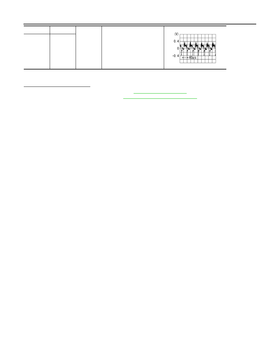
B554
*1
24
Ground
When DVD, USB or front AUX im-
age is displayed on headrest dis-
play unit LH or RH.
B574
*2
24
SKIB2251J