Infiniti QX56 (Z62). Manual - part 5


  Index      Infiniti     Infiniti QX56 (Z62) - service repair manual 2011 year


Search            


Content   ..  3  4  5  6   ..


Infiniti QX56 (Z62). Manual - part 5


SYSTEM

ADP-13

< SYSTEM DESCRIPTION >

C

D

E

F

G

H

I

K

L

M

A

B

ADP

N

O

P

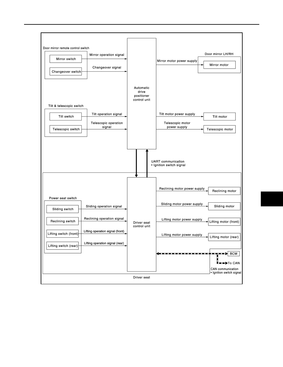
MANUAL FUNCTION : System Diagram

INFOID:0000000006248305

MANUAL FUNCTION : System Description

INFOID:0000000006248306

The driving position (seat, steering column and door mirror position) can be adjusted manually with power seat
switch, tilt & telescopic switch and door mirror remote control switch.

OPERATION PROCEDURE

1.

Turn ignition switch ON.

2.

Operate power seat switch, tilt & telescopic switch or door mirror remote control switch.

3.

The driver seat, steering column or door mirror operates according to the operation of each switch.

NOTE:
Seat operates only up to two places at the same time.

JMJIA3774GB

ADP-14

< SYSTEM DESCRIPTION >

SYSTEM

DETAIL FLOW

Seat 

NOTE:
The power seat can be operated manually regardless of the ignition switch position.

Tilt & Telescopic

Door Mirror

NOTE:
The door mirrors can be operated manually when ignition switch is in either ACC or ON position.

MEMORY FUNCTION

Order

Input

Output

Control unit condition

1

Power seat switch
(sliding, lifting, reclin-
ing)

The power seat switch signal is inputted to the driver seat control 
unit when the power seat switch is operated.

2

Motors
(sliding, lifting, reclin-
ing)

The driver seat control unit outputs signals to each motor accord-
ing to the power seat switch input signal.

Order

Input

Output

Control unit condition

1

Tilt & telescopic switch

The tilt & telescopic switch signal is inputted to the automatic 
drive positioner control unit when the tilt & telescopic switch is op-
erated.

2

Motors
(Tilt, telescopic)

The automatic drive positioner control unit actuates each motor 
according to the operation of the tilt & telescopic switch.

Order

Input

Output

Control unit condition

1

Door mirror remote 
control switch

The door mirror remote control switch signal is inputted to the au-
tomatic drive positioner control unit when the door mirror remote 
control switch is operated.

2

Motors
(Door mirror motor)

The automatic drive positioner control unit actuates each motor 
according to the operation of the door mirror remote control switch.

SYSTEM

ADP-15

< SYSTEM DESCRIPTION >

C

D

E

F

G

H

I

K

L

M

A

B

ADP

N

O

P

MEMORY FUNCTION : System Diagram

INFOID:0000000006248307

MEMORY FUNCTION : System Description

INFOID:0000000006248308

The driver seat control unit can store the optimum driving positions (seat, steering column and door mirror
position) for 2 people. If the front seat position is changed, one-touch (pressing desired memory switch) oper-
ation allows changing to the other driving position.
NOTE:
Further information for the memory storage procedure. Refer to  

ADP-53, "MEMORY STORING : Description"

OPERATION PROCEDURE

1.

Turn ignition switch ON.

2.

Shift position P position.

JMJIA3775GB

ADP-16

< SYSTEM DESCRIPTION >

SYSTEM

3.

Push desired memory switch.

4.

Driver seat, steering and door mirror will move to the memorized position.

OPERATION CONDITION

Satisfy all of the following items. The memory function is not performed if these items are not satisfied.

*

 : When timer function does not operate.

DETAIL FLOW

TIMER FUNCTION

• The memory function can be performed for 45 seconds after opening the driver door even if the ignition

switch position is in OFF position.

• Satisfy all of the following items. The timer function is not performed if these items are not satisfied.

Item

Request status

Ignition position

ON

*

Switch inputs
• Power seat switch
• Tilt & telescopic switch
• Door mirror control switch
• Set switch
• Memory switch

OFF

(Not operated)

A/T shift selector

P position

Memory function

Registered

Vehicle speed

0 Km/h (0 MPH)

CONSULT-III

Not connected

Order

Input

Output

Control unit condition

1

Memory switch

The memory switch signal is inputted to the driver seat control unit 
when memory switch 1 or 2 is operated.

2

Motors
(Seat, Steering, 
door mirror)

Driver seat control unit operates each motor of seat when it recogniz-
es the memory switch pressed for 0.5 second or more and requests 
each motor operation to automatic drive positioner control unit via 
UART communication. The automatic drive positioner control unit op-
erates each motor.

Memory switch Indica-
tor

Driver seat control unit requests the flashing of memory indicator 
while either of the motors is operating. The driver seat control unit il-
luminates the memory indicator.

3

Sensors
(Seat, steering col-
umn, door mirror)

Driver seat control unit judges the operating seat position with each 
seat sensor input. The positions of the steering column and outside 
mirror are monitored with each sensor signal. Driver seat control unit 
stops the operation of each motor when each part reaches the record-
ed address.

4

Memory switch Indica-
tor

Driver seat control unit requests the illumination of memory indicator 
after all motors stop. The driver seat control unit illuminates the mem-
ory indicator for 5 seconds.

Item

Request status

Ignition position

OFF

Set switch/memory switch

OFF

Memory function

Registered

A/T shift selector

P position

Steering lock unit status

LOCK

Driver side door switch

OFF

CUNSULT-III

Not connected


Content   ..  3  4  5  6   ..