Infiniti QX4 (R50). Manual - part 538
Part
SRS is activated
SRS is NOT activated
Harness and Connec-
tors
1. Check connectors for poor connection, damage, and terminals for deformities.
2. Check harness for binding, chafing, cuts, or deformities.
3. If no damage is found, reinstall the harness and connectors.
4. Damaged—REPLACE damaged section of harness. Do not attempt to repair, splice or modify any SRS
harness.
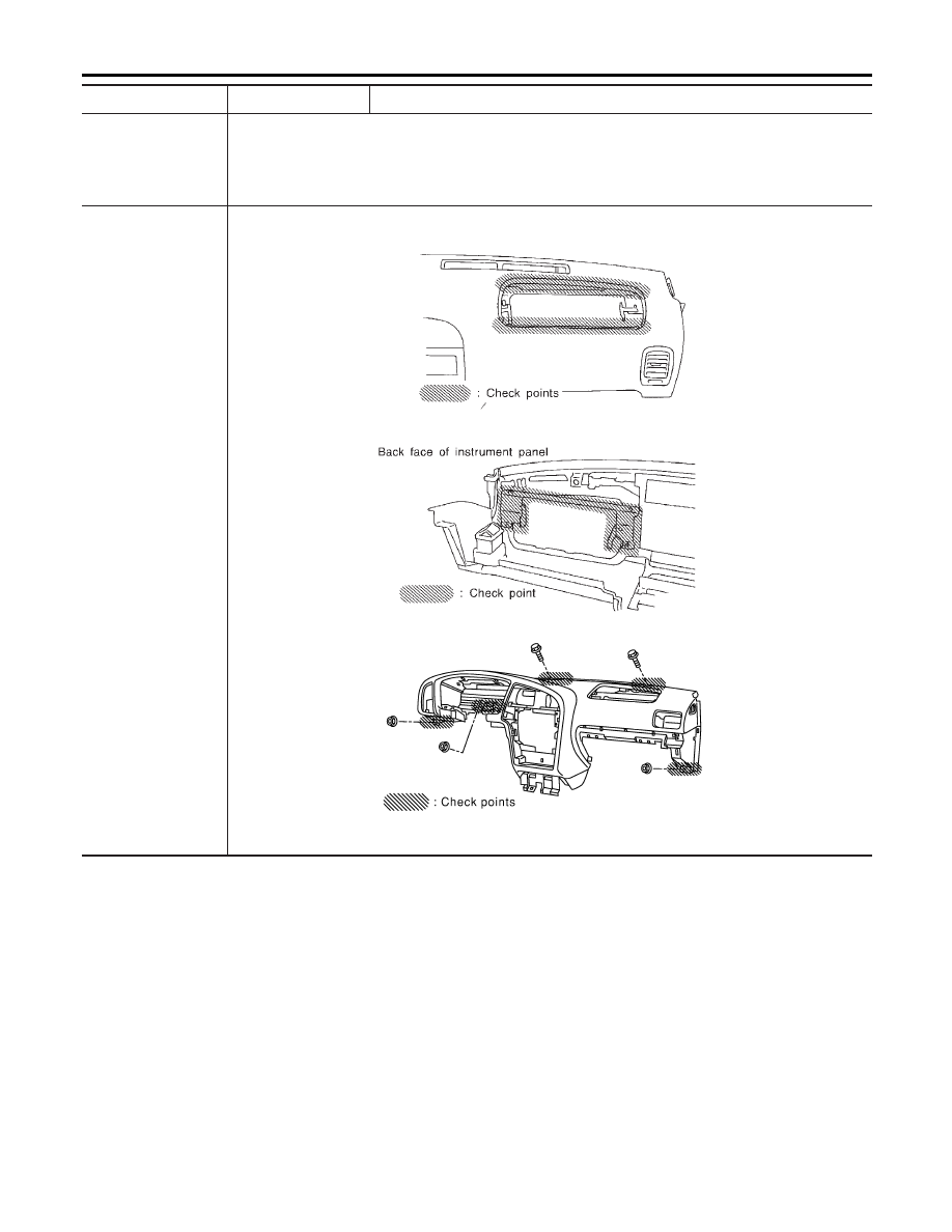
Instrument panel
1. When passenger air bag inflates, check the following points for bending, deformities or cracks.
I
Opening portion for passenger air bag
SRS366
I
Passenger air bag module brackets
SRS367
I
The portions securing the instrument panel
SRS876
2. If no damage is found, reinstall the instrument panel.
3. If damaged—REPLACE the instrument panel with bolts.
SUPPLEMENTAL RESTRAINT SYSTEM (SRS)
Collision Diagnosis (Cont’d)
RS-60