Infiniti QX4 (R50). Manual - part 206


  Index      Infiniti     Infiniti QX4 (R50) - service repair manual 2001 year


Search            copyright infringement  


Content   ..  204  205  206  207   ..


Infiniti QX4 (R50). Manual - part 206


Diagnostic Procedure

NBEC0168

1

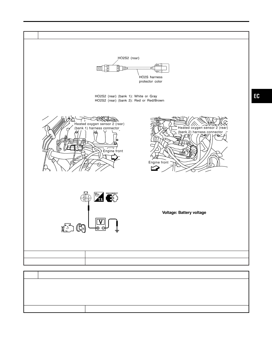
CHECK HO2S2 (REAR) POWER SUPPLY CIRCUIT

1. Turn ignition switch “OFF”.
2. Check heated oxygen sensor harness 2 (rear) protector color.

SEF372Z

3. Disconnect corresponding heated oxygen sensor 2 (rear) harness connector.

SEF971Y

4. Turn ignition switch “ON”.
5. Check voltage between HO2S2 terminal 3 and ground.

SEF314X

OK or NG

OK

©

GO TO 3.

NG

©

GO TO 2.

2

DETECT MALFUNCTIONING PART

Check the following.

I

Harness connectors M32, F23

I

Fuse block (J/B) connector M10

I

15A fuse

I

Harness for open or short between heated oxygen sensor 2 (rear) and fuse

©

Repair harness or connectors.

GI

MA

EM

LC

FE

AT

TF

PD

AX

SU

BR

ST

RS

BT

HA

SC

EL

IDX

DTC P0141, P0161 HEATED OXYGEN SENSOR 2 HEATER (REAR) (BANK 1)/

(BANK 2)

Diagnostic Procedure

EC-291

3

CHECK HO2S2 (REAR) OUTPUT CIRCUIT FOR OPEN AND SHORT

1. Turn ignition switch “OFF”.
2. Disconnect ECM harness connector.
3. Check harness continuity between ECM terminal and HO2S2 terminal as follows.

Refer to Wiring Diagram.

MTBL0529

Continuity should exist.

4. Also check harness for short to ground and short to power.

OK or NG

OK

©

GO TO 4.

NG

©

Repair open circuit or short to ground or short to power in harness or connectors.

4

CHECK HEATED OXYGEN SENSOR 2 HEATER (REAR)

Check the resistance between HO2S2 terminals as follows.

SEF315X

CAUTION:

Discard any heated oxygen sensor which has been dropped from a height of more than 0.5 m (19.7 in) onto a
hard surface such as a concrete floor; use a new one.

OK or NG

OK

©

GO TO 6.

NG

©

GO TO 5.

5

REPLACE HEATED OXYGEN SENSOR 2 (REAR)

Check heated oxygen sensor 2 harness (rear) protector color.

SEF372Z

CAUTION:

Before installing new oxygen sensor, clean exhaust system threads using Oxygen Sensor Thread Cleaner tool
J-43897-18 or J-43897-12 and approved anti-seize lubricant.

©

Replace malfunctioning heated oxygen sensor 2 (rear).

DTC P0141, P0161 HEATED OXYGEN SENSOR 2 HEATER (REAR) (BANK 1)/

(BANK 2)

Diagnostic Procedure (Cont’d)

EC-292

6

CHECK INTERMITTENT INCIDENT

Refer to “TROUBLE DIAGNOSIS FOR INTERMITTENT INCIDENT”, EC-140.

©

INSPECTION END

GI

MA

EM

LC

FE

AT

TF

PD

AX

SU

BR

ST

RS

BT

HA

SC

EL

IDX

DTC P0141, P0161 HEATED OXYGEN SENSOR 2 HEATER (REAR) (BANK 1)/

(BANK 2)

Diagnostic Procedure (Cont’d)

EC-293

On Board Diagnosis Logic

NBEC0169

With the Air/Fuel Mixture Ratio Self-Learning Control, the actual
mixture ratio can be brought closely to the theoretical mixture ratio
based on the mixture ratio feedback signal from the heated oxygen
sensors 1 (front). The ECM calculates the necessary compensation
to correct the offset between the actual and the theoretical ratios.
In case the amount of the compensation value is extremely large
(The actual mixture ratio is too lean.), the ECM judges the condi-
tion as the fuel injection system malfunction and light up the MIL
(2 trip detection logic).

Sensor

Input Signal to ECM

ECM func-

tion

Actuator

Heated oxygen sensors 1 (front)

Density of oxygen in exhaust gas
(Mixture ratio feedback signal)

Fuel injec-
tion control

Injectors

Malfunction is detected when fuel injection system does not oper-
ate properly, the amount of mixture ratio compensation is too large.
(The mixture ratio is too lean.)

Possible Cause

NBEC0487

I

Intake air leaks

I

Heated oxygen sensor 1 (front)

I

Injectors

I

Exhaust gas leaks

I

Incorrect fuel pressure

I

Lack of fuel

I

Mass air flow sensor

SEF968Y

DTC Confirmation Procedure

NBEC0170

NOTE:
If “DTC Confirmation Procedure” has been previously conducted,
always turn ignition switch “OFF” and wait at least 10 seconds
before conducting the next test.

WITH CONSULT-II

NBEC0170S01

1)

Start engine and warm it up to normal operating temperature.

2)

Turn ignition switch “OFF” and wait at least 10 seconds.

3)

Turn ignition switch “ON” and select “SELF-LEARN CON-
TROL” in “WORK SUPPORT” mode with CONSULT-II.

4)

Clear the self-learning control coefficient by touching “CLEAR”.

5)

Select “DATA MONITOR” mode with CONSULT-II.

6)

Start engine again and let it idle for at least 10 minutes.
The 1st trip DTC P0171 or P0174 should be detected at this
stage, if a malfunction exists. If so, go to “Diagnostic
Procedure”, EC-298.

7)

If it is difficult to start engine at step 6, the fuel injection sys-
tem has a malfunction, too.

8)

Crank engine while depressing accelerator pedal. If engine
starts, go to “Diagnostic Procedure”, EC-298. If engine does
not start, check exhaust and intake air leak visually.

DTC P0171 (RIGHT, -B1), P0174 (LEFT, -B2) FUEL INJECTION SYSTEM

FUNCTION (LEAN)

On Board Diagnosis Logic

EC-294


Content   ..  204  205  206  207   ..