Infiniti QX4 (R50). Manual - part 108


  Index      Infiniti     Infiniti QX4 (R50) - service repair manual 2001 year


Search            copyright infringement  


Content   ..  106  107  108  109   ..


Infiniti QX4 (R50). Manual - part 108


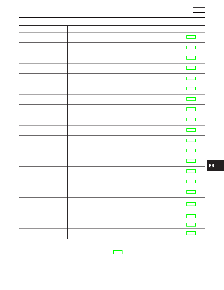
SELF-DIAGNOSTIC RESULTS MODE

NBBR0097S02

Diagnostic item

Diagnostic item is detected when ...

Reference Page

FR RH SENSOR*1
[OPEN]

I

Circuit for front right wheel sensor is open.
(An abnormally high input voltage is entered.)

BR-56

FR LH SENSOR*1
[OPEN]

I

Circuit for front left wheel sensor is open.
(An abnormally high input voltage is entered.)

BR-56

RR RH SENSOR*1
[OPEN]

I

Circuit for rear right sensor is open.
(An abnormally high input voltage is entered.)

BR-56

RR LH SENSOR*1
[OPEN]

I

Circuit for rear left sensor is open.
(An abnormally high input voltage is entered.)

BR-56

FR RH SENSOR*1
[SHORT]

I

Circuit for front right wheel sensor is shorted.
(An abnormally low input voltage is entered.)

BR-56

FR LH SENSOR*1
[SHORT]

I

Circuit for front left wheel sensor is shorted.
(An abnormally low input voltage is entered.)

BR-56

RR RH SENSOR*1
[SHORT]

I

Circuit for rear right sensor is shorted.
(An abnormally low input voltage is entered.)

BR-56

RR LH SENSOR*1
[SHORT]

I

Circuit for rear left sensor is shorted.
(An abnormally low input voltage is entered.)

BR-56

ABS SENSOR*1
[ABNORMAL SIGNAL]

I

Teeth damage on sensor rotor or improper installation of wheel sensor.
(Abnormal wheel sensor signal is entered.)

BR-56

FR RH IN ABS SOL
[OPEN, SHORT]

I

Circuit for front right inlet solenoid valve is open.
(An abnormally low output voltage is entered.)

BR-59

FR LH IN ABS SOL
[OPEN, SHORT]

I

Circuit for front left inlet solenoid valve is open.
(An abnormally low output voltage is entered.)

BR-59

FR RH OUT ABS SOL
[OPEN, SHORT]

I

Circuit for front right outlet solenoid valve is open.
(An abnormally low output voltage is entered.)

BR-59

FR LH OUT ABS SOL
[OPEN, SHORT]

I

Circuit for front left outlet solenoid valve is open.
(An abnormally low output voltage is entered.)

BR-59

RR IN ABS SOL
[OPEN, SHORT]

I

Circuit for rear inlet solenoid valve is shorted.
(An abnormally high output voltage is entered.)

BR-59

RR OUT ABS SOL
[OPEN, SHORT]

I

Circuit for rear out solenoid valve is shorted.
(An abnormally high output voltage is entered.)

BR-59

ABS ACTUATOR RELAY
[ABNORMAL]

I

Actuator solenoid valve relay is ON, even if control unit sends off signal.

I

Actuator solenoid valve relay is OFF, even if control unit sends on signal.

BR-59

ABS MOTOR RELAY
[ABNORMAL]

I

Circuit for ABS motor relay is open or shorted.

I

Circuit for actuator motor is open or shorted.

I

Actuator motor relay is stuck.

BR-61

BATTERY VOLT
[VB-LOW]

I

Power source voltage supplied to ABS control unit is abnormally low.

BR-63

CONTROL UNIT

I

Function of calculation in ABS control unit has failed.

BR-68

G SENSOR*2
[ABNORMAL]

I

G sensor circuit is open or shorted.

BR-65

*1: If one or more wheels spin on a rough or slippery road for 40 seconds or more, the ABS warning lamp will illuminate. This does not
indicate a malfunction. Only in the case of the short-circuit (Code Nos. 26, 22, 32 and 36), after repair the ABS warning lamp also illu-
minates when the ignition switch is turned ON. In this case, drive the vehicle at speeds greater than 30 km/h (19 MPH) for approxi-
mately 1 minute as specified in “SELF-DIAGNOSIS PROCEDURE”, BR-41. Check to ensure that the ABS warning lamp goes out while
the vehicle is being driven.
*2: 4WD models only

GI

MA

EM

LC

EC

FE

AT

TF

PD

AX

SU

ST

RS

BT

HA

SC

EL

IDX

ON BOARD DIAGNOSTIC SYSTEM DESCRIPTION

ABS

CONSULT-II Inspection Procedure (Cont’d)

BR-45

PBR455D

DATA MONITOR PROCEDURE

NBBR0097S03

1.

Turn ignition switch OFF.

2.

Connect CONSULT-II to data link connector.

3.

Turn ignition switch ON.

4.

Touch “START” on CONSULT-II screen.

SBR670E

5.

Touch “ABS”.

SBR636E

6.

Touch “DATA MONITOR”.

SBR637E

7.

Touch “SETTING” on “SELECT MONITOR ITEM” screen.

ON BOARD DIAGNOSTIC SYSTEM DESCRIPTION

ABS

CONSULT-II Inspection Procedure (Cont’d)

BR-46

PBR455D

ACTIVE TEST PROCEDURE

=NBBR0097S04

I

When conducting Active test, vehicle must be stationary.

I

When ABS warning lamp stays on, never conduct Active test.

1.

Turn ignition switch OFF.

2.

Connect CONSULT-II to data link connector.

3.

Start engine.

4.

Touch “START” on CONSULT-II screen.

SBR670E

5.

Touch “ABS”.

SBR636E

6.

Touch “ACTIVE TEST”.

SBR671E

7.

Select active test item by touching screen.

SBR639E

8.

Touch “START”.

9.

Carry out the active test by touching screen key.

GI

MA

EM

LC

EC

FE

AT

TF

PD

AX

SU

ST

RS

BT

HA

SC

EL

IDX

ON BOARD DIAGNOSTIC SYSTEM DESCRIPTION

ABS

CONSULT-II Inspection Procedure (Cont’d)

BR-47

DATA MONITOR MODE

NBBR0097S05

MONITOR ITEM

CONDITION

SPECIFICATION

FR RH SENSOR
FR LH SENSOR
RR RH SENSOR
RR LH SENSOR

Drive vehicle.
(Each wheel is rotating.)

Wheel speed signal
(Almost the same speed as speedometer.)

STOP LAMP SW

Brake is depressed.

Depress the pedal: ON
Release the pedal: OFF

G-SWITCH

Vehicle is driven.
Vehicle is stopped.
Brake is applied.

During sudden braking while driving on high µ roads (asphalt
roads, etc.): OFF
While vehicle is stopped or during constant-speed driving: ON

FR RH IN SOL
FR RH OUT SOL
FR LH IN SOL
FR LH OUT SOL
RR IN SOL
RR OUT SOL

1. Drive vehicle at speeds
over 30 km/h (19 MPH) for at
least 1 minute.
2. Engine is running.

Operating conditions for each solenoid valve are indicated. ABS
is not operating: OFF

MOTOR RELAY

ABS is not operating: OFF
ABS is operating: ON

ACTUATOR RELAY

Ignition switch is ON or
engine is running.

Ignition switch ON (Engine stops): OFF
Engine running: ON

WARNING LAMP

ABS warning lamp is turned on: ON
ABS warning lamp is turned off: OFF

BATTERY VOLT

Power supply voltage for control unit

ABS OPER SIG

ABS is not operating: OFF
ABS is operating: ON

: 4WD model only

ACTIVE TEST MODE

NBBR0097S06

TEST ITEM

CONDITION

JUDGEMENT

FR RH SOLENOID
FR LH SOLENOID
RR SOLENOID

Engine is running.

Brake fluid pressure control operation

IN SOL

OUT SOL

UP (Increase):

OFF

OFF

KEEP (Hold):

ON

OFF

DOWN (Decrease):

ON

ON

ABS MOTOR

ABS actuator motor
ON: Motor runs (ABS motor relay ON)
OFF: Motor stops (ABS motor relay OFF)

ABS OPER SIG

Ignition switch is ON or
engine is running.

ON: Set ABS OPER SIG “ON” (ABS is operating.)
OFF: Set ABS OPER SIG “OFF” (ABS is not operating.)

G SWITCH

Ignition switch is ON.

G SWITCH (G SENSOR)
ON: Set G SWITCH MONITOR “ON” (G switch circuit is
closed.)
OFF: Set G SWITCH MONITOR “OFF” (G switch circuit is
open.)

: 4WD models only

NOTE:
Active test will automatically stop ten seconds after the test starts. (TEST IS STOPPED monitor shows ON.)

ON BOARD DIAGNOSTIC SYSTEM DESCRIPTION

ABS

CONSULT-II Inspection Procedure (Cont’d)

BR-48


Content   ..  106  107  108  109   ..