Infiniti Q45. Manual - part 886
 

  Index      Infiniti     Infiniti Q45 - service repair manual 2006 year


Search            copyright infringement  


Content   ..  884  885  886  887   ..


Infiniti Q45. Manual - part 886


TROUBLE DIAGNOSIS

STC-47

[WITH REAR ACTIVE STEER]

C

D

E

F

H

I

J

K

L

M

A

B

STC

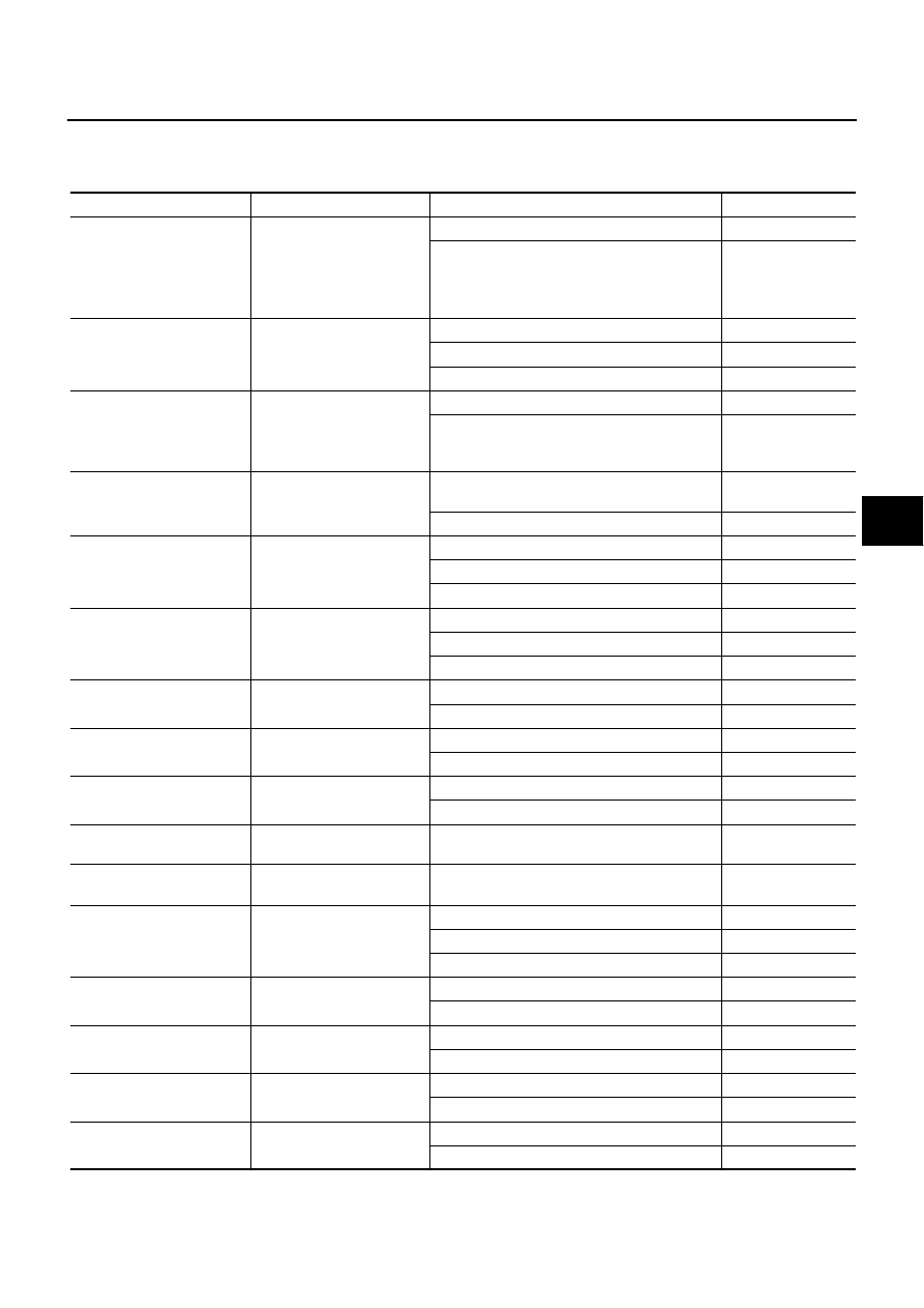
RAS Control Unit Input/Output Signal Reference Values

NGS0006R

RAS CONTROL UNIT INSPECTION TABLE
Specifications with CONSULT-II

Monitor item [Unit]

Content

Condition

Display value

VHCL SPEED SE [km/h] or 
[mph]

Wheel speed

Vehicle stopped

0 km/h (0 MPH)

Vehicle running

CAUTION:

Check air pressure of tire under standard 
condition.

Approximately equal 

to the indication on 

speedometer (Inside 

of 

±

10%)

STEERING ANG [

°

]

Steering angle detected by 
steering angle sensor

Steering wheel right turned

0

°

 - R756

°

Straight-ahead

Approx. 0

°

Steering wheel left turned

0

°

 - L756

°

ENGINE SPEED [rpm]

Engine speed

Engine stopped

0 rpm

Engine running
(Engine speed: 400 rpm or more)

Approximately equal 

to the indication on 

tachometer

POWER STR SOL [A]

Monitored value of current at 
power steering solenoid 
valve

Vehicle speed: 0 km/h (0 MPH)
(Engine is running)

Approx. 1.10 A

Vehicle speed: 100 km/h (62 MPH)

Approx. 0.54 A

RR ST ANG-MAI [V]

Rear wheel steering angle 
(main) sensor output voltage

RAS actuator assembly turned full right

Approx. 4.4 V

RAS actuator assembly neutral

Approx. 2.4 V

RAS actuator assembly turned full left

Approx. 0.4 V

RR ST ANG-SUB [V]

Rear wheel steering angle 
(sub) sensor output voltage

RAS actuator assembly turned full right

Approx. 4.4 V

RAS actuator assembly neutral

Approx. 2.4 V

RAS actuator assembly turned full left

Approx. 0.4 V

RR ST ANG-VOL [V]

Rear wheel steering angle 
sensor input voltage

Ignition switch: ON

Approx. 5 V

Ignition switch: OFF

0 V

C/U VOLTAGE [V]

Power supply voltage for 
RAS control unit

Ignition switch: ON

Battery voltage

Ignition switch: OFF

MOTOR VOLTAGE [V]

Monitored value of voltage 
at RAS motor

Ignition switch: ON

Battery voltage

Ignition switch: OFF

0 V

MOTOR CURRENT [A]

Monitored value of current at 
RAS motor

During RAS actuator assembly turning

Approx. 0 - 20 A

MTR CRNT OPE [A]

Current commanded value 
to RAS motor

During RAS actuator assembly turning

Approx. -20 - 20 A

RR ANGLE OPE [

°

]

Rear wheel steering angle 
detected by rear wheel 
steering angle sensor

RAS actuator assembly turned full right

Approx. 1

°

RAS actuator assembly neutral

Approx. 0

°

RAS actuator assembly turned full left

Approx. -1

°

STOP LAMP SW [ON/OFF]

Stop lamp condition

Brake pedal: Depressed

ON

Brake pedal: Released

OFF

HICAS RELAY [ON/OFF]

RAS motor relay condition

Ignition switch: ON

ON

Ignition switch: OFF

OFF

FAIL SAFE [ON/OFF]

Fail-safe condition

Fail-safe condition

ON

Normal

OFF

WARNING LAMP [ON/OFF]

RAS warning lamp condition

RAS warning lamp: ON

ON

RAS warning lamp: OFF

OFF

STC-48

[WITH REAR ACTIVE STEER]

TROUBLE DIAGNOSIS

Specifications Between RAS Unit Terminals

RAS CONTROL UNIT CONNECTOR LAYOUT

Data are reference value and are measured between each terminal and ground.

SGIA1449E

Terminal

Wire 

color

Item

Condition

Data (Approx.)

1

L

CAN-H

4

G

Rear wheel steering angle (main) 
sensor output voltage

RAS actuator assembly turned full right

4.4 V

RAS actuator assembly neutral

2.4 V

RAS actuator assembly turned full left

0.4 V

5

W

Power supply
(rear wheel steering angle sensor)

Ignition switch: ON

5 V

Ignition switch: OFF

0 V

7

R

Rear wheel steering angle (sub) 
sensor output voltage

RAS actuator assembly turned full right

4.4 V

RAS actuator assembly neutral

2.4 V

RAS actuator assembly turned full left

0.4 V

8

P

CAN-L

15

B

Ground
(rear wheel steering angle sensor)

Always

0 V

22

L/B

Stop lamp switch

Brake pedal: Depressed

Battery voltage

Brake pedal: Released

0 V

25

L/W

RAS motor relay

Ignition switch: ON

Battery voltage

Ignition switch: OFF

0 V

26

G/W

RAS warning lamp

RAS warning lamp: ON

1.4 V or less

RAS warning lamp: OFF

Ignition voltage: 
2.8 V or more

27

GY

Ignition switch

Ignition switch: ON

Battery voltage

Ignition switch: OFF

0 V

34

B

Ground

Always

0 V

36

LG

Power steering solenoid valve

Vehicle speed: 0 km/h (0 MPH)
(Engine is running)

4.4 - 6.6 V

Vehicle speed: 100 km/h (62 MPH)

2.4 - 3.6 V

37

L/Y

Power supply
(RAS motor)

Ignition switch: ON

Battery voltage

Ignition switch: OFF

0 V

38

G/Y

RAS motor output voltage
(right)

While RAS motor is operating for right

Battery voltage

While RAS motor is operating for left

0 V

39

G/R

RAS motor output voltage
(left)

While RAS motor is operating for right

0 V

While RAS motor is operating for left

Battery voltage

40

B

Ground
(RAS motor)

Always

0 V

TROUBLE DIAGNOSIS

STC-49

[WITH REAR ACTIVE STEER]

C

D

E

F

H

I

J

K

L

M

A

B

STC

CAUTION:

When using a circuit tester to measure voltage for inspection, be sure not to extend forcibly any connector terminals.

CONSULT-II Function (RAS/HICAS)

NGS0006S

FUNCTION

CONSULT-II can display each diagnostic item using the diagnostic test modes shown following.

CONSULT-II SETTING PROCEDURE

Refer to 

GI-36, "CONSULT-II Start Procedure"

 .

SELF-DIAG RESULT MODE
Operation Procedure

1.

Perform “CONSULT-II Start Procedure”. Refer to 

GI-36, "CONSULT-II Start Procedure"

 .

2.

With engine at idle, touch “SELF-DIAG RESULTS”.
Display shows malfunction experienced since the last erasing operation.

NOTE:
The details for “TIME” are as follows:

“0”: Error currently detected with active damper suspension control unit.

Except for “0”: Error detected in the past and memorized with active damper suspension control unit.
Detects frequency of driving after DTC occurs (frequency of turning ignition switch “ON/OFF”).

Display Item List

Diagnostic test mode

Function

Reference 

page

Self-diagnostic results

Self-diagnostic results can be read and erased quickly.

STC-49

Data monitor

Input/Output data in the RAS control unit can be read.

STC-51

CAN diagnostic support monitor

The results of transmit/receive diagnosis of CAN communication can be read.

LAN-29

Active test

Sends a drive signal to RAS motor to check each sensor operation.

STC-52

ECU part number

RAS control unit part number can be read.

STC-53

Items 

(CONSULT-II screen terms)

Diagnostic item is detected when...

Check item

CONTROL UNIT
[ABNORMAL1]
[C1900]

Malfunction has occurred inside RAS control unit.

STC-56, "DTC C1900, 
C1901, C1905, C1906, 
C1907, C1908, C1922, 
C1927, C1928 CONTROL 
UNIT"

CONTROL UNIT
[ABNORMAL2]
[C1901]

Malfunction has occurred inside RAS control unit.

STC-56, "DTC C1900, 
C1901, C1905, C1906, 
C1907, C1908, C1922, 
C1927, C1928 CONTROL 
UNIT"

MOTOR OUTPUT
[REV CURRENT]
[C1902]

The current flows in the opposite direction when the RAS motor cur-
rent is output. 

STC-57, "DTC C1902, 
C1903, C1904, C1910, 
C1913 MOTOR OUTPUT"

MOTOR OUTPUT
[NO CURRENT]
[C1903]

The current flows when the RAS motor current is not output. 

STC-57, "DTC C1902, 
C1903, C1904, C1910, 
C1913 MOTOR OUTPUT"

MOTOR OUTPUT
[OVERCURRENT]
[C1904]

The excessive high current flows when the RAS motor current is out-
put.

STC-57, "DTC C1902, 
C1903, C1904, C1910, 
C1913 MOTOR OUTPUT"

CONTROL UNIT
[ABNORMAL3]
[C1905]

AD converter system of RAS control unit is malfunctioning.

STC-56, "DTC C1925 AD 
CONVERTER"

STC-50

[WITH REAR ACTIVE STEER]

TROUBLE DIAGNOSIS

CONTROL UNIT
[ABNORMAL5]
[C1906]

Malfunction has occurred inside RAS control unit.

STC-56, "DTC C1900, 
C1901, C1905, C1906, 
C1907, C1908, C1922, 
C1927, C1928 CONTROL 
UNIT"

CONTROL UNIT
[ABNORMAL4]
[C1907]

Malfunction has occurred inside RAS control unit.

STC-56, "DTC C1900, 
C1901, C1905, C1906, 
C1907, C1908, C1922, 
C1927, C1928 CONTROL 
UNIT"

CONTROL UNIT
[ABNORMAL7]
[C1908]

Malfunction has occurred inside RAS control unit.

STC-56, "DTC C1900, 
C1901, C1905, C1906, 
C1907, C1908, C1922, 
C1927, C1928 CONTROL 
UNIT"

CONTROL UNIT
[ABNORMAL6]
[C1909]

Malfunction has occurred inside (ignition signal) RAS control unit.

STC-60, "DTC C1909 CON-
TROL UNIT"

MOTOR OUTPUT
[MOTOR LOCK]
[C1910]

When 17A or more current flows to the motor, the rear wheel steering 
angle sensor signal does not change for some time.

STC-57, "DTC C1902, 
C1903, C1904, C1910, 
C1913 MOTOR OUTPUT"

MOTOR VOLTAGE
[LOW VOLTEGE]
[C1911]

The RAS motor power supply voltage is lower than ignition power sup-
ply voltage with RAS motor relay ON.

STC-62, "DTC C1911, C1912 
MOTOR VOLTAGE"

MOTOR VOLTAGE
[BAD OBSTRCT]
[C1912]

The RAS motor power supply voltage is inputting for some time with 
RAS motor power supply OFF by RAS control unit.

STC-62, "DTC C1911, C1912 
MOTOR VOLTAGE"

MOTOR OUTPUT
[ABNORML SIG]
[C1913]

When the RAS motor current value is 10 A or more, actual output is 
excessively low and the condition continues for some time.

STC-57, "DTC C1902, 
C1903, C1904, C1910, 
C1913 MOTOR OUTPUT"

RR ST ANGLE SENSOR
[ABNORML VOL]
[C1914]

Higher or lower value compared to the standard voltage.

STC-67, "DTC C1914, 
C1915, C1916, C1917, 
C1918 RR ST ANGLE SEN-
SOR"

RR ST ANGLE SENSOR
[MAIN SIGNAL]
[C1915]

The rear wheel steering angle sensor (main) input signal is malfunc-
tioning for some time against the sensor power supply value.

STC-67, "DTC C1914, 
C1915, C1916, C1917, 
C1918 RR ST ANGLE SEN-
SOR"

RR ST ANGLE SENSOR
[SUB SIGNAL]
[C1916]

When the main sensor input signal is 2.4 - 2.6 V, the rear wheel steer-
ing angle sensor (sub) input signal is malfunctioning for some time 
compared to the sensor power supply value.

STC-67, "DTC C1914, 
C1915, C1916, C1917, 
C1918 RR ST ANGLE SEN-
SOR"

RR ST ANGLE SENSOR
[OFFSET SIG1]
[C1917]

An excessive difference has occurred in the input values of rear wheel 
steering angle sensor (main) and rear wheel steering angle sensor 
(sub).

STC-67, "DTC C1914, 
C1915, C1916, C1917, 
C1918 RR ST ANGLE SEN-
SOR"

RR ST ANGLE SENSOR
[OFFSET SIG2]
[C1918]

An excessive difference has occurred in the input values of rear wheel 
steering angle sensor (main) and rear wheel steering angle sensor 
(sub).

STC-67, "DTC C1914, 
C1915, C1916, C1917, 
C1918 RR ST ANGLE SEN-
SOR"

VEHICLE SPEED SEN
[NO SIGNAL]
[C1919]

Malfunction is detected in vehicle speed signal that is output from 
VDC/TCS/ABS control unit through CAN communication.

Improper signal is input while driving.

STC-72, "DTC C1919 VEHI-
CLE SPEED SEN"

STEERING ANGLE SEN
[NO SIGNAL]
[C1920]

No steering angle signal is input for some time.

STC-72, "DTC C1920, 
C1923, C1924, C1926 
STEERING ANGLE SEN"

Items 

(CONSULT-II screen terms)

Diagnostic item is detected when...

Check item


Content   ..  884  885  886  887   ..