Infiniti Q45. Manual - part 824


  Index      Infiniti     Infiniti Q45 - service repair manual 2006 year


Search            copyright infringement  


Content   ..  822  823  824  825   ..


Infiniti Q45. Manual - part 824


AUTOMATIC DRIVE POSITIONER

SE-51

C

D

E

F

G

H

J

K

L

M

A

B

SE

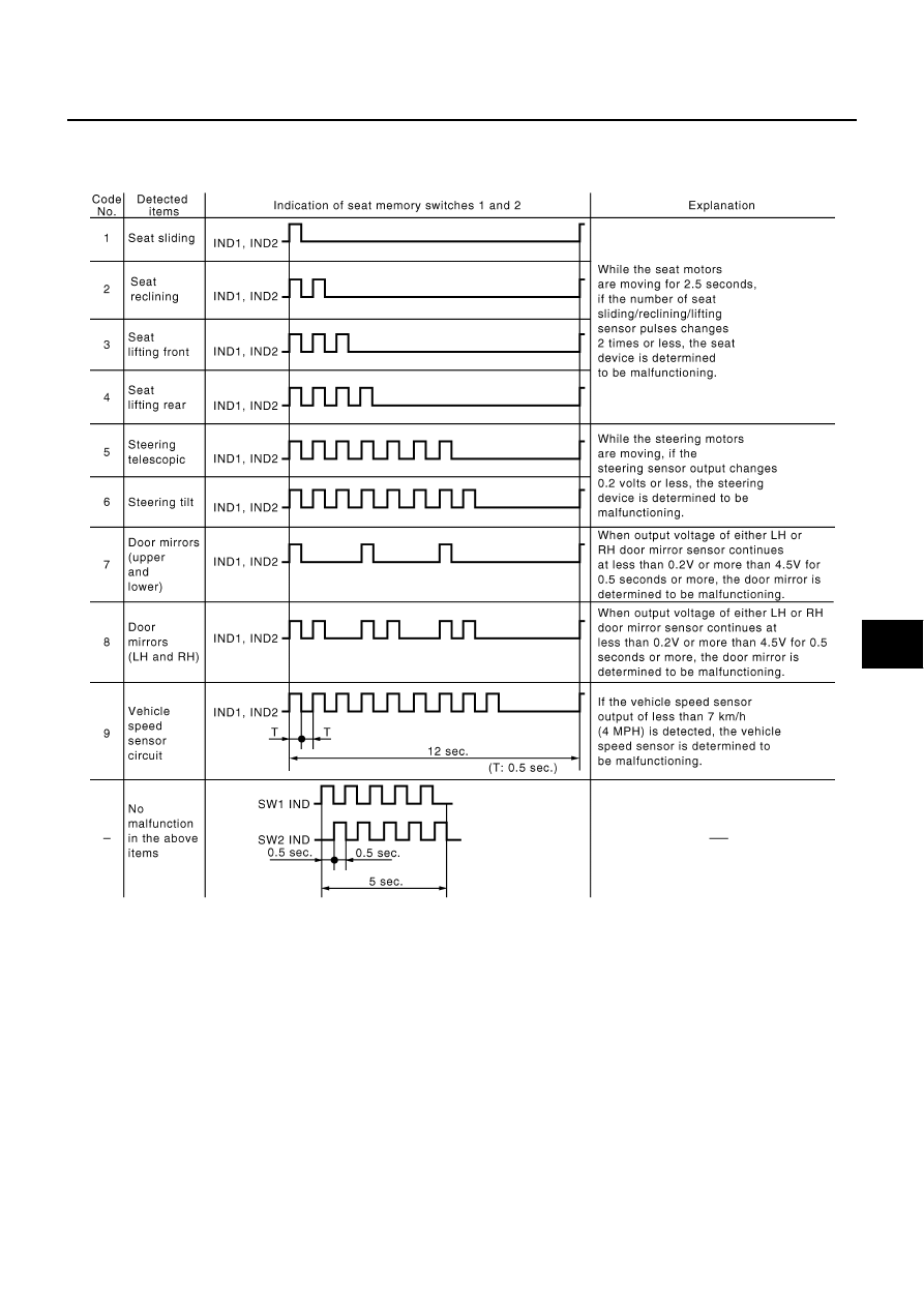
Diagnostic Result Display

The malfunctioning items are indicated by how many times LEDs on the seat memory switches 1 and 2
flash simultaneously.

If the vehicle speed is less than 7 km/h (4 MPH) for 15 seconds after the diagnosis for the seat and steer-
ing wheel systems were completed, the vehicle speed signal is judged malfunctioning.

If LH door mirror is malfunctioning, only indicator lamp on the memory switch 1 flashes, and if RH door
mirror is malfunctioning, only indicator lamp on the memory switch 2 flashes.

When all the diagnosis are finished normally, the indicator lamps on the memory switches 1 and 2 go off
after the vehicle speed signal diagnosis.

If there are multiple malfunctioning parts, the lamps indicate them in sequence from the smallest diagno-
sis trouble code.

The diagnosis results repeat until the diagnosis mode is cancelled.

PIIA0190E

SE-52

AUTOMATIC DRIVE POSITIONER

Symptom Chart

NIS0012P

Symptom

Diagnoses / service procedure

Refer to 

page

A part of seat system does not operate 
(both automatically and manually).

1.

Check sliding motor circuit

SE-54

2.

Check reclining motor circuit

SE-55

3.

Check front lifting motor circuit

SE-65

4.

Check rear lifting motor circuit

SE-58

5.

If the above systems are normal, replace the BCM

A part of steering wheel system does not operate 
(both  automatically and manually).

1.

Check telescopic motor circuit

SE-59

2.

Check tilt motor circuit

SE-61

3.

If the above systems are normal, replace the BCM

 Door mirrors cannot be actuated in both automatic and 
manual modes.

1.

Check door mirror remote control switch (changeover 
switch) circuit

GW-108

2.

Check door mirror remote control switch (mirror switch) 
system

GW-111

3.

If the above systems are normal, replace the BCM

A part of seat system does not operate 
(only automatic operation).

1.

Check sliding sensor circuit

SE-63

2.

Check reclining sensor circuit

SE-64

3.

Check front lifting sensor circuit

SE-65

4.

Check rear lifting sensor circuit 

SE-66

5.

If the above systems are normal, replace the driver seat 
control unit

Door mirrors cannot be actuated  in automatic mode.

1.

Check back-up input signal circuit in R position

GW-110

2.

Check mirror sensors circuit

GW-114

3.

If the above systems are normal, replace the door mirror 
control unit

All the automatic operations do not operate.

1.

Check detention switch circuit

SE-67

2.

Check telescopic sensor circuit

SE-68

3.

Check tilt sensor circuit

SE-69

4.

Check vehicle speed signal 

SE-73

5.

If all the above systems are normal, replace the BCM

Seat or steering wheel memory does not work.

1.

Check seat memory switch circuit

SE-75

2.

If the above systems are normal, replace the BCM

Only manual operation does not operate.

1.

Check sliding switch circuit

SE-76

2.

Check reclining switch circuit 

SE-78

3.

Check front lifting switch circuit 

SE-80

4.

Check rear lifting switch circuit 

SE-82

5.

Check telescopic switch circuit 

SE-84

6.

Check tilt system switch circuit 

SE-86

7.

Check door mirror remote control switch (mirror switch) 
circuit

GW-111

8.

If all the above systems are normal, replace the driver seat 
control unit for the seat system, the BCM for the steering 
wheel system

The entry / exiting does not operated when door is 
opened and closed 
(The entry / exiting operates with key switch)

1.

Check seat memory indicator lamp circuit

SE-88

2.

If the above systems are normal, replace the BCM

AUTOMATIC DRIVE POSITIONER

SE-53

C

D

E

F

G

H

J

K

L

M

A

B

SE

Seat memory indicator lamps 1 and 2 do not illuminate.

1.

Check front door switch (driver side) circuit

SE-72

2.

If the above systems are normal, replace the BCM

Auto driving position system self-diagnosis does not 
work. (With out CONSULT-II)

1.

Check detention switch circuit

SE-67

2.

Check key switch and key lock solenoid circuit

SE-70

3.

Check seat memory switch circuit

SE-75

4.

Check seat memory indicator lamp circuit

SE-88

5.

Check vehicle speed signal 

SE-73

6.

If all the above systems are normal, retry the self-diagnosis. 
If the self-diagnosis are still disable, check the driver seat 
control unit connector and terminals for looseness and 
damage

Lumber support motor does not operated.

Check lumber support circuit

SE-89

Turnout operation of rear power seat LH does not 
operate, bat rear power seat can be operated by rear 
power seat switch.

Check rear power seat turnout operation.

SE-91

Symptom

Diagnoses / service procedure

Refer to 

page

SE-54

AUTOMATIC DRIVE POSITIONER

Check Sliding Motor Circuit

NIS0012Q

1. 

CHECK SEAT SLIDING MECHANISM

Check the following.

Operation malfunction caused by sliding rail deformation or pinched harness or other foreign materials

Operation malfunction caused by foreign materials adhered to the sliding motor or sliding rail connector
rod

Operation malfunction and interference with other parts by poor installation

OK or NG

OK

>> GO TO 2.

NG

>> Repair the malfunction part and check again.

2. 

CHECK FUNCTION

With CONSULT-II

Check operation with "SEAT SLIDE" in ACTIVE TEST. 

Without CONSULT-II

Perform the on-board diagnosis. Refer to 

SE-50, "ON BOARD DIAGNOSIS FOR AUTOMATIC DRIVE POSI-

TIONER"

 .

OK or NG

OK

>> System is OK.

NG

>> GO TO 3.

3. 

CHECK HARNESS CONTINUITY

1.

Turn ignition switch OFF.

2.

Disconnect driver seat control unit connector and sliding motor connector.

3.

Check continuity between driver seat control unit connector
B142 terminals 1, 8 and sliding motor connector B146 terminals
1, 8.

4.

Check continuity between driver seat control unit connector
B142 terminals 1, 8 and ground.

OK or NG

OK

>> GO TO 4.

NG

>> Repair or replace harness between driver seat control unit and sliding motor.

Test item

Description

SEAT SLIDE

The sliding motor is activated by receiving the drive signal.

PIIA0265E

1 (W) – 1 (W)

: Continuity should exist.

8 (BR) – 8 (BR)

: Continuity should exist.

1 (W) – Ground

:Continuity should not exist.

8 (BR) – Ground

:Continuity should not exist.

PIIA2921E


Content   ..  822  823  824  825   ..